CNC 4th Axis
This is my CNC 4th axis that I built for my CNC Gantry Mill.
Design
The first thing I started looking at was using a standard horizontal/vertical rotary table...
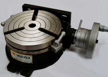
These solid chunks of steel are driven by a worm gear giving a ratio of 90 turns of the handle to 1 revolution of the table. Unfortunately, there is a lot of backlash in this gearing. When I use the rotary table on the mill/drill, I have to use the lock down clamps to hold the position. I have read that the backlash can be removed, just not how.
The next idea was to use this beast, a NSK Megatorque motor.
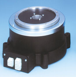
The megatorque motor is a slow moving, high accuracy, high torque motor. I found a model YSB2020 on ebay, with controller, for $600. This motor has an output torque of 20Nm, and a maximum speed of 180 rpm. It runs off 240v and has a step/direction input. The only real negative with this motor is its size. I planned to mount it to an angle plate as shown in the CAD drawing below...
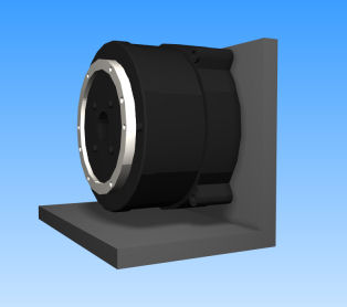
The angle plate is 250x180x150 which is a bit too big to fit on the CNC Gantry mill. This motor was put away for another project.
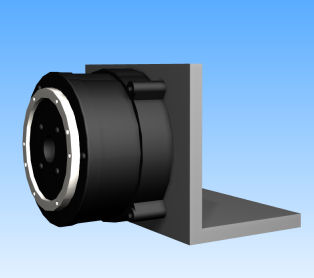
Finally I found the ideal motor. I found this combo on ebay...
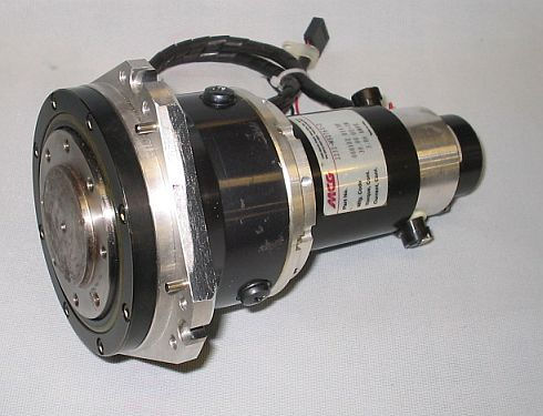
The motor is a brushed DC motor, with a kV of 7.6 volts per 1000 rpm, a maximum speed of 6000rpm, a 1000 line encoder and a continuous output torque of 30 oz-in. 30 oz-in is pretty weak for a rotary axis, but what makes this combination special is the big chunk of harmonic drive on the front. It's a 100:1, zero backlash inline gearbox. That pumps the torque up from 30 oz-in to 3000 oz-in (180 lb-in, 21Nm) ignoring inefficiencies.
It's also compact and fits nicely on a small angle plate. CAD comparison picture below...
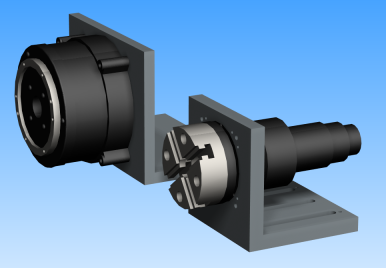
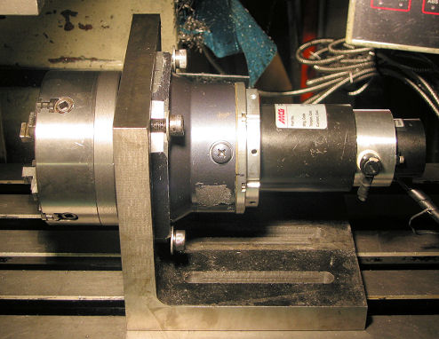
This combination produced a much more compact unit, even with a 4-jaw chuck attached in the picture (no jaws shown).
A harmonic drive is a pretty cool device. Its basically an oval shaped gear running inside a circular shaped gear. There's a good description of it on the harmonic drive website. Here's a link to an animation from the description page showing how the drive works. Notice how fast the big arrow at the center rotates compared to the one on the outside.
Construction
Angle Plate
This was a pretty simple build. The best fitting angle plate I could find was 6"x6"x6". I found one with no slots machined in it so I could cut the hole to mount the drive. However I couldn't find one without webbing, so there was a bit of work machining that off.
The angle plate to be machined was mounted on the mill table using another angle plate. This allowed me to work on the front faces of the angle plate that I was machining. This is shown below.
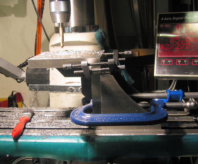
The two faces of the angle plate had to be machined. One face will have a large hole for the harmonic drive, and its mounting holes. The other face will have bolt down slots.
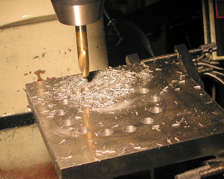
To cut the large hole, 100mm diameter, I started by drilling a bolt circle of closely placed holes close to the outside dimension of the circle. The holes were spaced apart slightly less than the diameter of the 10mm spot drill I was using. Once this was done, I shifted the bolt circle start angle and drilled the holes between the existing holes until the middle of the hole fell out. Hopefully the pictures describe it better.
The first set of holes...
Then the next lot. There is one more hole to drill...
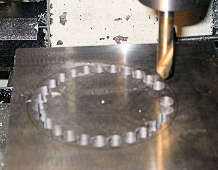
And through...
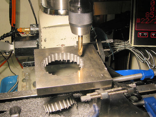
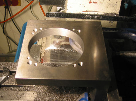
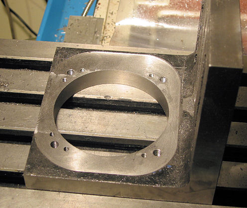
Finally, the whole was cleaned up with the boring head, and the mounting holes drilled and tapped.
Next, the angle plate was flipped over so the face we just machined was clamped to the mill table. This is so we can create the mounting face for the harmonic gearbox. I used a face mill with 90° corners so I could get close to the angle plate corner. Unfortunately, the face mill was only 50mm in diameter. The mill spindle hit angle plate before the face mill got all the way into the corner.
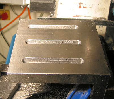
Finally, the plate was remounted using another angle plate and the bottom mounting slots were machined. These slots match the 8mm t-slots on my gantry mill.
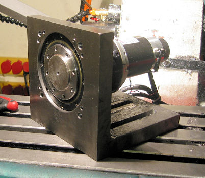
And here's a shot of the motor mounted to the base.
Next, the mounting plates.
Mounting Plates
The harmonic drive has a boss on the front and a series of mounting holes. This means a mounting plate has to be mounted from the front. And it also means a chuck has to be bolted on from the front, so that restricted my choice of chucks.
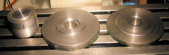
The mounting plates where machined from pieces of cast iron, 200mm in diameter and 20mm thick that I got from minitech (not a listed product, but I asked when I bought the chuck). I bought two pieces: one for a mounting plate for the chuck and the other for a faceplate.
The first step was to mount the plates in the 4 jaw chuck then machine the back face, bore the center hole and machine the register. This is shown in the photo below. I just had enough clearance.
The completed machining is shown in the photo below, just before the mounting holes were drilled. The large cylinder of metal on the left is the mounting block that will be used to hold the plates concentrically in the lathe for machining of the front faces. This has been machined oversize, so it can be finished after the mounting holes are drilled to ensure concentricity.
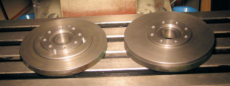
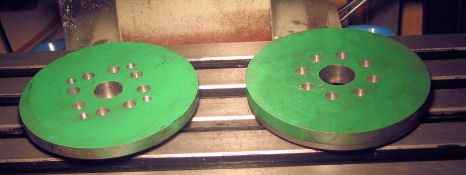
The plates were clamped to the table and drilled. The faceplate only has a circle of holes. The mounting plate for the chuck has the circle of holes and threaded holes for the chuck.
Next, the mounting block was put back in the lathe and centered. Then a finishing cut was made to get the register to the correct dimension, and to make it concentric. The mounting block is shown below.
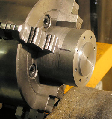
Next the mounting plate was bolted to the block. The piece of cast iron for the chuck mount was too large, so I trimmed it with the bandsaw before turning it, hence the octagon shape. This probably saved an hour or two of turning on my 9x20 lathe.
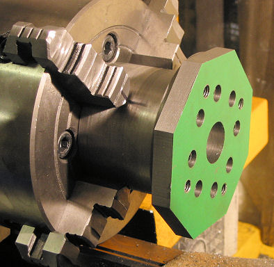
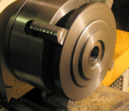
Finally, the chuck mounting plate is machined to size.
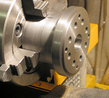
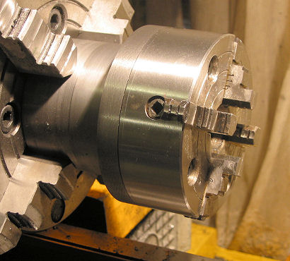
And tested..
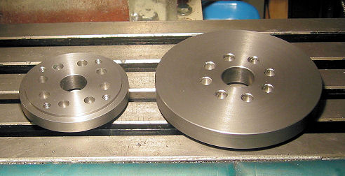
This was repeated for the faceplate. I'm not sure how I am going to use the face plate at the moment, so it has been left blank. I will probably machine some t-slots in it, either in a radial pattern, or maybe just parallel slots. I'll wait until the first job.
Assembly
The photo below shows the mechanical assembly. I only used 4 large bolts to hold the gearbox to the angle plate. I got the positioning wrong on the smaller ones. Doh!
The wiring was all packed away into a small aluminium electronics enclosure. I used CB microphone style connectors to connect to the drive. I separated the encoder and motor signals. The encoder signals are differential, so I used some shield twisted pair cable to run it to the electrical cabinet. For the motor wiring, I used standard AC 3 core flex, using 2 wires for the DC, and the third as a motor chassis ground. I used the last of my braided cable shield to cover the motor cable, then covered that in some bright yellow heat shrink tubing.
The drive is controlled by a Gecko G320 servo drive, using a 24v power supply. I could probably increase the voltage to 40 volts, but it seems to run fine at 24v.
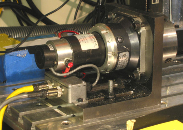
The completed 4th axis is shown below.
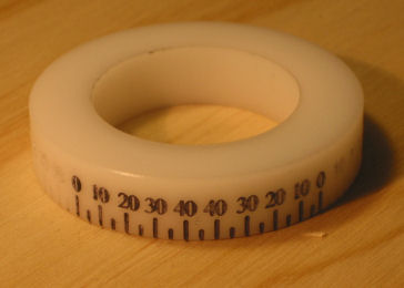
The first job for the 4th axis was engraving the numbers on one of the many Quorn dials. I started with a test run in a piece delrin. The results are shown below. Some of numbers have been painted with a black sharpie.