Mill
I already had my RF-31 Mill/Drill form Hare and Forbes when I decided to build a CNC mill. Being the cautious type, I didn't want to start with a CNC retrofit on the mill/drill in case I stuffed it up.
Design
My initial inspiration came from the 5 Bears Research website. The website has a great write-up of the construction of a mill, using bits and pieces collected from eBay.
I went in a different direction than 5bears. Firstly, I decided to build a gantry style mill. I was expecting the whole thing to be light duty, so I thought it would be easier to move around a fixed weight gantry rather than have issues moving around the changing weight of a table and work piece. I also wanted to ensure the NC Mill had an equal or greater cutting area to my mill/drill so I decided to build it using complete linear assemblies, rather than try and machine something more complex.
With an idea in my mind, I started collecting bits and pieces.
My first big find was a pair of used KR3310B-500, with 200W Yaskawa servo motors and SGDE-02AP drivers for $400 each. I didn't know it at the time, but the "P" in the driver model name meant it worked in position mode; these drivers are hard to find. The slides have 335mm of travel. These will be used for the Z-Axis - yes, both of them.
I also found a pair of brand new KR4610D-740LP for $600 each. This was a bit pricey, but they were brand new, in the manufacturers box, 573mm of travel, and have dual carriages. Perfect for the Y axis. I have a pair of Reliance 480 Watt, 168 oz-in DC brushed motors, and a pair of G320s to drive them
Another nice find was a Parker 406XR300 slide assembly. This assembly has a table mounted on two slide rails and is driven by a ballscrew. It came with a motor, a SM233BE-NFNL, which I wasn't planning on using until I read the specifications for it and found out how powerful it was. I found a driver for it, a Parker TQ10, which only ran on 110v, so I also needed a transformer. This was used for the X-axis.
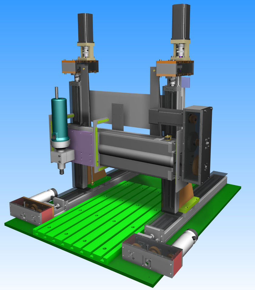
The CAD design of the mill is shown below. Click on them for larger images. (Normally I'd provide the 3d pdf file, but Alibre Design crashes when I try to create it - what's new)
Base
The whole assembly is mounted on a 12mm thick aluminium plate (dark green in the picture above). The plate has holes tapped to mount the KR46 Y axis slides. There is only about 0.5mm play in the mounting holes so the tapped holes had to be very parallel. On top of the base plate is the T-slot table (bright green). This was machined out of 25mm aluminium plate. The plan was to be able to remove this and bolt on a plate with tapped holes as an option. I haven't needed to do this yet.
Z Axis
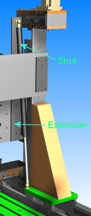
The two KR33 slides are used to move move the whole X assembly up and down, rather than just the spindle. I thought that would give more rigidity so I could cut steel. One leg of the Z axis is shown below.
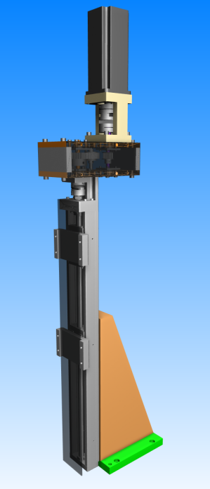
The Z axis is mounted to the trucks of the Y axis through the green base plate. A large, 60mm thick, triangular chunk of aluminium (orange) holds the KR33 slide upright. At the top of the slide is a timing belt gear box with a 4:1 ratio. On top of that is Yaskawa 200W servo motor, connected by an adaptor. The motor couldn't be connected to the gearbox directly because the spindle of the motor is 14mm in diameter, which couldn't be bored properly in a 20 tooth GT3 pulley.
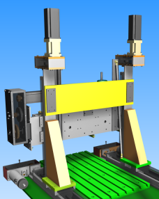
A bracing plate is bolted to the back of the two Z assemblies to keep them parallel to each other. This is highlighted in yellow in the image below.
A gas strut/spring is connected between the base of each Z axis and an extension bar on the X axis to help carry the weight of the X assembly. The X assembly, without spindle, is about 15kg, so to 7.5kg struts are used (I forgot to allow for the spindle weight). The extension was necessary because the the extended length of the strut is more than twice the working distance. The extension creates the longer distance. I got the struts from Aussie Gas Strut Co. They were about $30 +GST each.
Y Axis
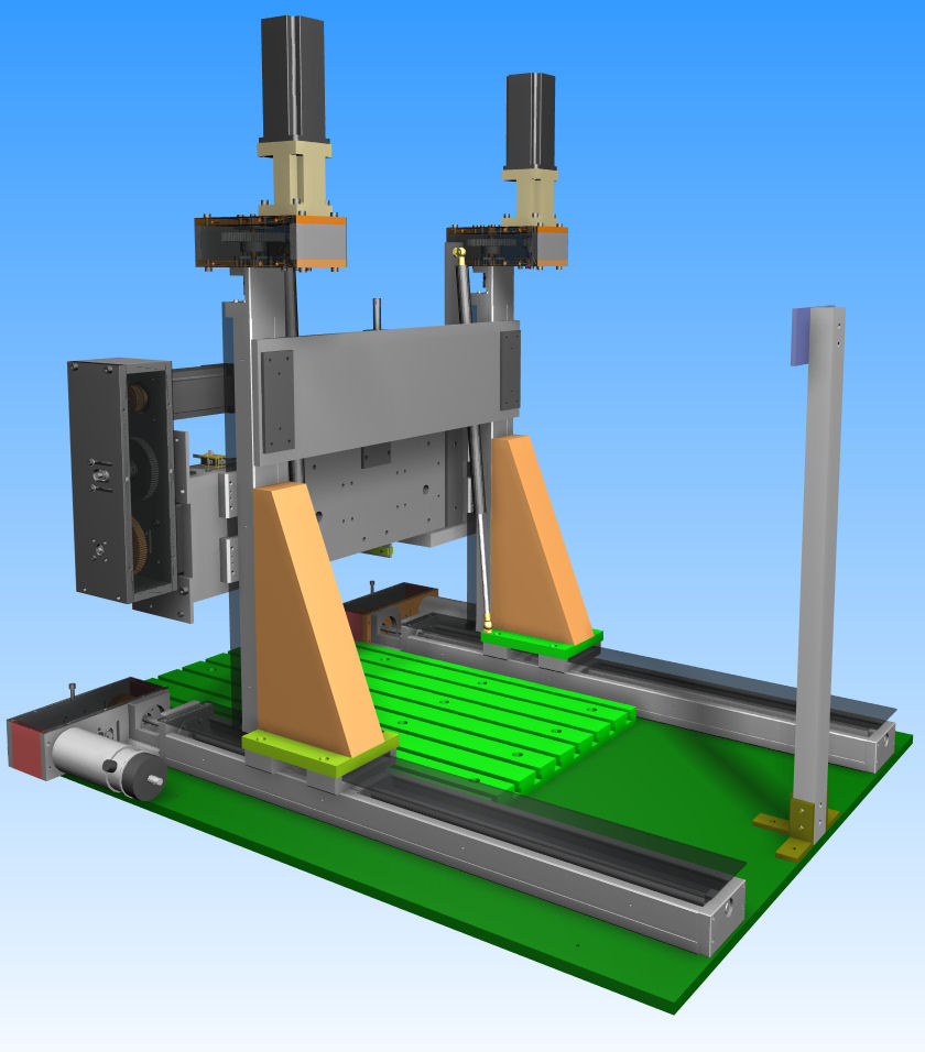
The Y axis is pretty simple, as shown in the picture below.
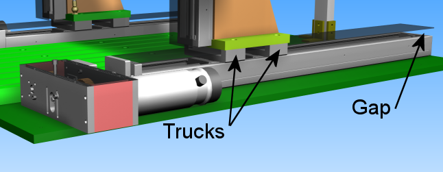
The KR46 slides are mounted parallel to each other on the base. The Z axis uprights are mounted to the two trucks on the KR46 slide. One of the trucks is driven by the ballscrew. The other moves freely. I have the "D" model KR46 with narrow trucks. In order to provide a rigid mount for the Z axis, the trucks are separated by an additional 60mm, which reduces the maximum travel.
On the end of the Y axis is a belt drive gear box and the motor. Originally there was no gear box and the motor was connected directly to the KR46 slide. That explains why parts stick out over the edge of the base. The motor is folded back so it doesn't protrude.
The picture above also shows the problem with the slide's lack of protection. There is a cover on each of the slides, but there remains a large gap that runs the length of the slide (ignore the floating cover in the picture - just a lazy CAD operator). The gap is at the exact height that a 2 ½D work piece would be mounted and the same height that chips and swarf will be flung out from the tool.
X Axis
The X axis too, was a simple implementation. It is a Parker 406XR300 slide assembly, mounted onto a backing plate, which is mounted to the trucks on the KR33 Z axis. The picture of the X axis is shown below.
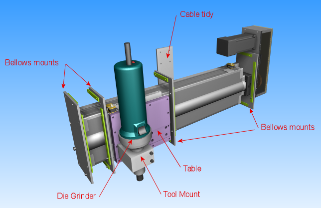
The CAD image shows the 406XR300 all sealed up. Unfortunately the slide I got was missing the strips used to seal the top, leaving large swarf collecting slots. To fix this, I've created bellows to cover most of the axis. The mounting plates for the bellows are shown in the picture. They are machined from 3mm steel.
On the right hand side is the belt drive gear reducer. It is an 8:1, two stage reducer. The motor is folded back to save space. Unfortunately this also means when the Z axis is at full travel, the motor hits the Z gear box. This means I lose about 10cm of Z travel. This needs to be fixed.
On the back of assembly is an aluminium plate used to tidy the cabling. Cables for the X axis motor and encoder, limit switches and home switches are tied to this plate.
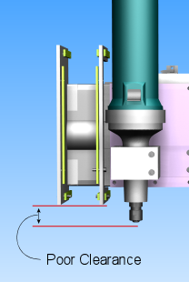
The slide assembly has a large table that was prefect for mounting spindles to. The picture shows my Bosch die grinder attached to it. Unfortunately, looks can be deceiving. The picture below shows the poor clearance that I have with the stock tool mount and the steel bellows mounts. I discovered this when table slammed into the hold down bolts I was using to clamp a work piece.
Gear ratios
I always planned to add reduction gearing to each of the axis. The 20mm pitch ballscrew on the X axis was a concern, whether it would be able to provide the torque I needed to machine wood, aluminium and steel. So how much torque do I need to machine these materials? I have no idea! I haven't really found any reliable source information. A suggestion on one forum was to attach a hanging scale to the handle of a manual mill and measure the torque that way! So I guessed 4:1 for Z and Y. Because the X axis had twice the ballscrew pitch, I made it 8:1. The table below shows the before and after speed and torque values.
| Axis | Motor RPM | Torque (oz-in) | Screw Pitch | Max Speed (mm/s) | Selected Ratio | Geared Torque (oz-in) | Geared Max Speed (mm/s) | Geared Max Speed (m/min) |
| X | 4000 | 150 | 20 | 1333 | 8:1 | 1200 | 166 | 10 |
| Y | 3000 | 180 | 10 | 500 | 4:1 | 720 | 125 | 7.5 |
| Z | 3000 | 150 | 10 | 500 | 4:1 | 400 | 125 | 7.5 |
Implementation
Here are some photos of my beast. Unfortunately, it is in a dark corner of my little workshop and it is hard to get good photos of it. If only I could rotate my room around in real life the way I can in a CAD program.
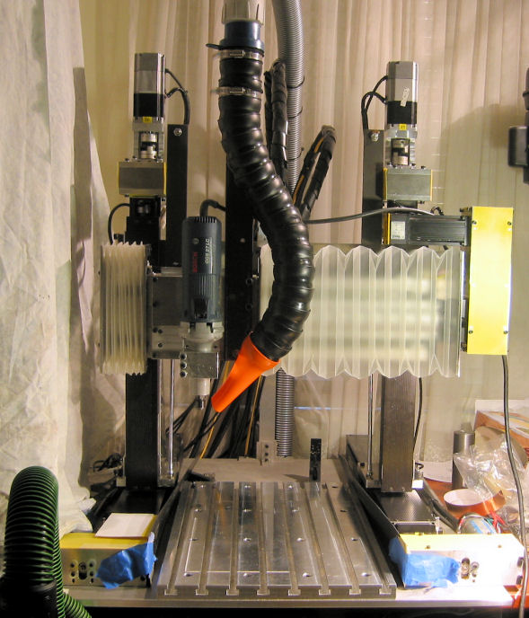
This is the front view. The bed sheet to the left covers the electrical cabinet. It confuses the photograph if it is visible. The bellows is installed on the X axis. Gear box covers are made of bright yellow plastic. I scavenged the plastic from some cheap plastic binders. The blue masking tape stuck to the Y axis gear boxes holds a long strip of plastic that covers the slots on the Y axis slides. This picture has my Bosch die grinder installed.
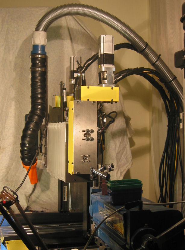
Here is the side view. You can see the wiring and vacuum hose running out the back. There are three bundles of wiring, one each for the X, Z1 and Z2 axes. In each bundle is the cable for the motor power, encoder, hi and low limit switches, home switch, and some 3/16" piano wire, which keeps the wire bending at a large radius. I saw someone do something similar to this on CNCZone. They used a sheet strip of spring steel which I couldn't source. Each bundle is held together with spiral cable wrap.
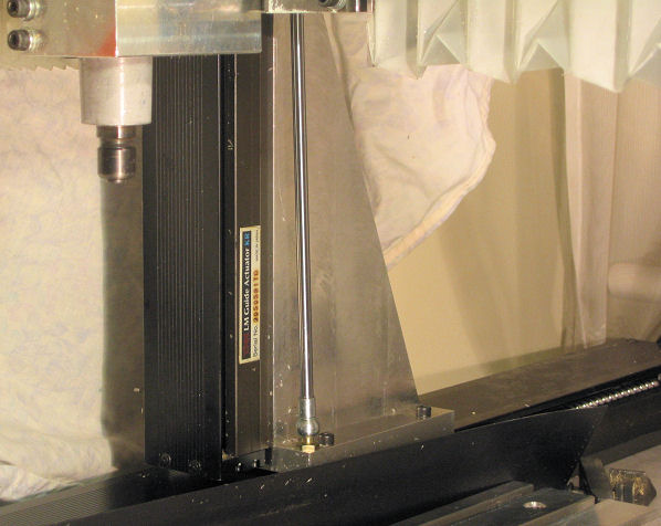
This photo shows the Z upright assembly. You can see the KR33 slide, the gas strut, and the beautiful aluminium triangle holding the KR33 square. To make the triangles (one on each Y axis), I started with a 300x200x65mm slab of aluminium. I couldn't use my regular vice to hold the slab because it wouldn't fit the work piece in the tall direction. I had to build a two piece vice to clamp the slab to the mill/drill table and machine the piece square. Once it was square, I drilled and tapped the mounting holes. Finally, the nicely squared slab was clamped to the mill/drill table and cut into two triangles using a 16mm, long shank slot drill. I'm really proud of my triangles.
And here's the electrical cabinet from hell....
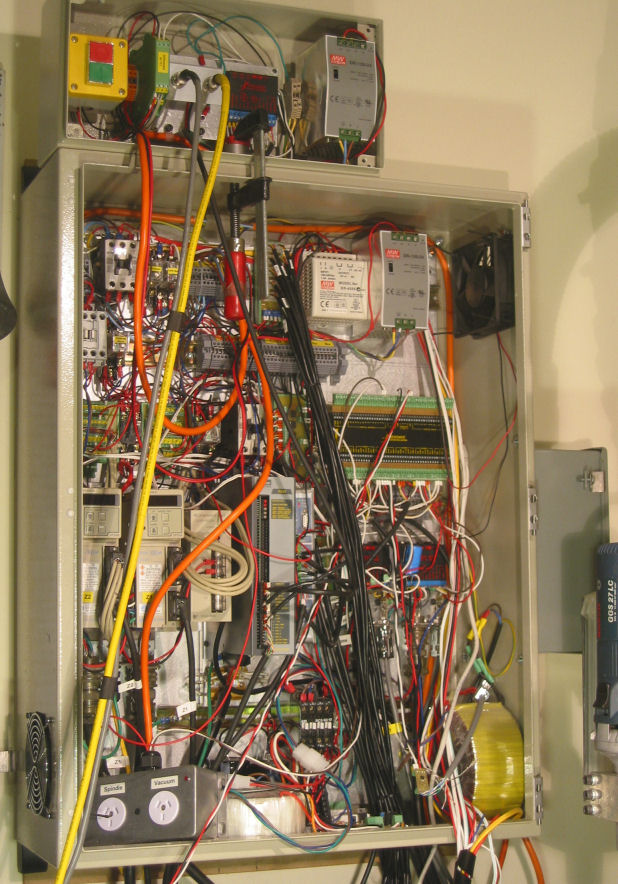
The enclosure is 800 x 600 x 250mm. It filled up very quickly - which is what happens when every axis has a different driver and each driver has its own power and control requirements. Hover over the image to see the components inside.
And finally, here is the control panel. This is installed in a box near the electrical cabinet until I decide what switches and lights I need, and I decide on a good way to install them on the cabinet door where I can keep changing my mind.
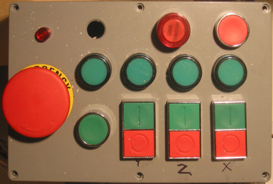
I have an emergency stop which cuts mains power to everything. A green start button that has to be pressed and held until the contactors switch on. Individual start and stop buttons for each axis, X, Y and Z. (the 4th axis also has one, but in its own little box). The system and each axis has an "on" light. There is also a limit override button and a red button to reset the G100 - sometimes the G100 doesn't start up properly and must be reset - which causes the Pixie and TQ10 on the X axis to fault.
Spindle
This should read "spindles". I won a couple of die grinders on ebay, a Bosch GGS 27LC, and a Metabo GSE7145. These are both rugged industrial die grinders. Both have long necks. Both are variable speed and have electronic speed control which will maintain the spindle speed under load. The Bosch is rated at 600W and has a speed range of 12,000rpm to 27,000rpm. The Metabo is rated at 710W and has a speed range from 2,000rpm to 7,000rpm. Unfortunately, both have inefficient universal motors which means the input power rating they state means the outputs power is only about 60% that. They are also very loud.
I have a full set of collets for each (3mm, 1/8", 6mm, ¼", 8mm), so I can use a large selection of tooling. The collets are precise, and I have yet to break any PCB drills on the mill. I mainly use the Bosch - for PCB drilling and routing, and wood working, at full speed. I plan to use the Metabo at slower speeds to cut steel.
Next
These are the things that need to be fixed...
- Covers for the Y and Z axes.
- Get a real spindle.
- Try and enclose the whole machine so dust and swarf doesn't spray everywhere.
- Fix or reposition the X gearbox so I get the full Z travel back.
- Re-wire the electrical cabinet. I have a 1200x1000x300 enclosure waiting to be used.
- Replace the G100 with the Smooth stepper.
- Work out the proper speeds and feeds for my spindles and tooling.
- Waterproof the machine so I can start cutting with cutting fluid. (or maybe find a way to silence my air compressor and use that).