Custom GenericHID Board
When building my custom CNC pendants using GenericHID and the AT90USBKey, I found access to board pins. It is doable, but when there are a lot of wires it gets tedious. So I built a simple break out board.
Version 1.0
My first version, Version 0.99, was a home made development board, a huge 170x110mm. About 90% of it was blank space. It used expensive removable terminal blocks which I needed while developing. Part of the reason for the size was my inability to produce proper PCB vias. So, when the GenericHID software and firmware was debugged, I built a proper board.
The image below show the board. Compared to an at90usbkey, it is still big.
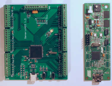
The board has 0.1" pitch terminal connectors installed on the board. It also has holes to install 0.1" dual row headers, so IDC type connectors can be used. There are holes for a JTAG connector and and a TTL RS232 connector. USB cable is connected via a mini-USB socket.
The board was made at BatchPCB. This link allows you to order a board directly from them GenericHID 1.0 Board Design. The board isn't cheap because of its size.
The parts can be order from most large electronics retailers. I got them from Digikey. This is the parts list that can be uploaded via Digikey's BOM Manager (I think you need a customer Id for this, but it's free)
Part's List - generichid1.0.csv
Ordering the parts from Digikey is pretty cool. Each lot of parts is individually packaged and labeled with the part number used on the board. This makes it very easy to build the board.
Part's List above includes all the parts to build the board. Some parts are optional. The list below shows them.
| Digi-Key Part Number | Board Reference | Quantity | Description | Comments |
| CKN9102-ND | S1, S2 | 2 | SWITCH TACT MOM 130GF H=5MM | These switches are used to reset the board and get it back into boot loader mode. Although optional, they are recommended for use when building a HID device. |
| A98074-ND | J1, J5, J7, J9, J11, J13, J15 | 7 | TERM BLOCK 10POS SIDE ENT 2.54MM | Optional terminal blocks. Wires can be soldered directly to the board, however these terminals, or the headers below are recommended. These terminals are quite expensive. |
| HRP10H-ND | J2, J6, J8, J10, J12, J14, J16 | 7 | CONN HEADER LOW-PRO 10POS GOLD | Optional headers. Wires can be soldered directly to the board, however these headers, or terminals above are recommended. These are cheaper than the terminals, but will also require suitable connectors. 1 of the connectors is used for the JTAG interface, which is only necessary if you have a JTAG debugger. |
| 311-1140-1-ND | C1, C2, C3, C4, C5, C7, C8 | 10 | CAP .10UF 50V CERAMIC X7R 0805 | |
| 399-1284-1-ND | C6, C12, C13, C14, C15, C16, C17 | 10 | CAP 1.0UF 16V CERAMIC X7R 0805 | |
| 495-1528-1-ND | C11 | 1 | CAP TANT 100UF 10V 10% LOESR SMD | |
| 311-1103-1-ND | C9, C10 | 10 | CAP CERAMIC 22PF 50V NP0 0805 | |
| 283-2535-1-ND | CR1, CR2 | 2 | SUPPRESSOR ESD 24VDC 0603 SMD | These suppressors are optional. They help suppress static discharge when connecting and disconnecting the USB device. Recommended. |
| 350-2045-1-ND | DS1 | 1 | LED INGAN GRN CLEAR 0805 SMD | This LED lights when USB 5v is present. It was a bad choice because it is super bright. |
| 67-1361-1-ND | DS2 | 1 | LED DUAL RED/GREEN CLR 1210 SMD | This LED shows the USB connection status. Optional. Ports PD5/PD6 are used by the LED. |
| A1912-ND | J4 | 1 | CONN HEADER VERT 4POS .100 TIN | Optional connector for the RS232 port. Only used when debugging. |
| H2959CT-ND | J3 | 1 | CONN RECEPT MINI USB2.0 5POS | This is an "oopsie!" component. There are 2 small plastic pins underneath that locate the part on the board. These don't match the holes and have to be removed before soldering. Use a knife or side cutters. The solder pins and mounting legs match the PCB fine. |
| NTR4101PT1GOSCT-ND | Q1 | 1 | MOSFET P-CH 20V 1.8A SOT-23 | |
| P0.0ACT-ND | R1, R8, R11 | 10 | RES 0.0 OHM 1/8W 5% 0805 SMD | |
| P1.0MACT-ND | R10 | 10 | RES 1.0M OHM 1/8W 5% 0805 SMD | |
| P22ACT-ND | R2, R3 | 10 | RES 22 OHM 1/8W 5% 0805 SMD | |
| P1.0KACT-ND | R4, R5, R9 | 10 | RES 1.0K OHM 1/8W 5% 0805 SMD | |
| P47KACT-ND | R6, R7 | 10 | RES 47K OHM 1/8W 5% 0805 SMD | |
| AT90USB1287-AU-ND | U1 | 1 | IC AVR MCU 128K 64TQFP | |
| 300-8421-ND | Y1 | 1 | CRYSTAL 8.000 MHZ CYL TYPE | The overlay on the PCB shows the placement of the crystal on the bottom side of the board. The crystal can be placed on the top layer and folded over the capacitors. |
The DIY board isn't cheap. The PCB is $25 + $10 handling + shipping. Parts, including the terminals is about $50 (terminals are $22.75 of that).
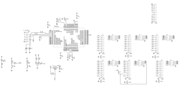
Here is the schematic of the board. Click on it for more details.
Known Issues
There are two issues with the board.
One is the size. The board wouldn't fit inside the enclosure for my latest pendant for my CNC lathe.
Two, is the USB connector. It is difficult to run a USB cable through the case of an enclosure without making an enormous hole. To make it work, I used a USB A to USB mini connector, cut off the USB A connector, threaded the cable through a cable gland and soldered on a new USB A connector. I had to do this to use a PG7 size cable gland. If you use a PG9 size cable gland, you may be able to squeeze the USB mini connector through after removing the plastic cover from the USB mini connector. The PG9 gland however is too big to hold the thin USB cable so the cable needs to be thickened with electrical tape.
This issues will be addressed with Custom GenericHID Board 1.1.