Limit Switches
Here's how I implemented my limit switches for the mill.
Requirements
I wanted the limit switches to stop the whole mill. Therefore, the limit switches are tied into the emergency stop system.
I also wanted to know which switch was tripped.
Design
The limit switch wiring schematic for 2 switches is shown below...
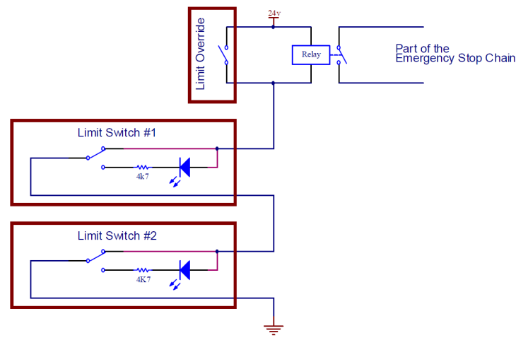
Points to note are...
- The limit switches make up a circuit to control the relay. This relay is part of the emergency stop chain. If this relay is open, there is no power to the system.
- The limit switches are logically chained together to form one long wire to ground.
- The limit switch is a SPDT switch, that is, it will complete one circuit if it is open, and a different circuit if it is closed.
- If the limit switch trips, it will switch the LED on. However, because of the current limiting resistor, not enough current will flow through the relay and it will switch off. This will shutdown the whole system, including the illuminated indicator LED.
- There is a limit override button that will allow the system to start up even if a switch is closed (limit hit). This will illuminate the tripped switch LED.
There are limitations.
- If a wire comes lose, or is broken, no LEDs will be lit.
- This method doesn't remember which switch tripped, so if something accidently bumped a switch, or there is an intermittent connection somewhere, this wont be shown.
I described the switches as being "Logically" chained together. This is because my implementation wires each limit switch directly back to a "Limit switch control panel". This is a PCB with connectors for each wire, which physically implements the chaining. More on this below.
Hardware
The limit switches use standard micro switches. I used these from my local electronics shop, Altronics, part number S3262.
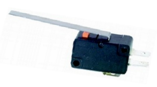
They are SPDT with a long lever. The long lever adds extra over travel, and gives them extra reach to hit the moving bit.
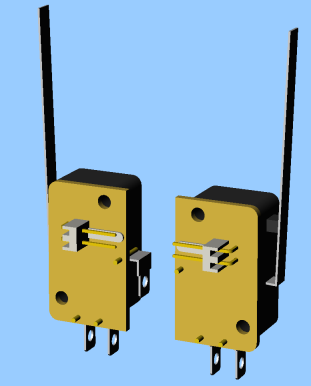
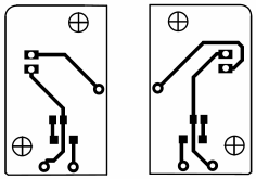
The PCB is mounted directly onto the switch, making the unit self contained. PCB Matrix pins connect the PCB to the microswitch. The design of the double sided PCB allows the switch to be mounted facing the left or the right, depending on which side of the board the parts are mounted to. This is shown below.
The schematic for the switch is shown below...
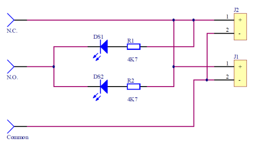
The "two of everything" is for left and right support. One half of the circuit is on one side of the PCB and the other is on the other side. The PCB layout is shown below.
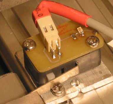
The connection from the PCB to the microswitch is done using PCB Matrix Pins. There are holes in the PCB at the correct position to connect with the microswitch's lugs. After these have been soldered, the lugs are cut off. The larger holes in the PCB are aligned with those on the microswitch to allow the whole assembly to be mounted.
Here is one of the switches mounted on my mill.
And here it is faulting.
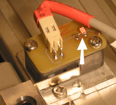
The photo doesn't show the effectiveness of the LED, but it is quite bright.
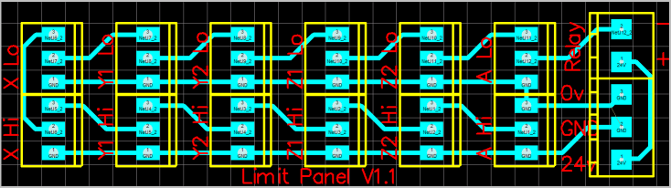
Limit Control Panel
All the limit switches on the mill run back to the limit control panel. The control panel does the chaining of switches. It will also allow me to easily change the way I process limit faults in the future.
The schematic is shown below. This version just brings together the external components - limit switches, power and relay. The Limit Override switch is wired in elsewhere.
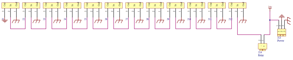
As you can see, it simply chains together the connectors. A shield pin is provided, but it isn't terribly useful in this situation.
The PCB is shown below.
Next Version
Apart from the limitations listed above, the biggest problem with this implementation was the connectors. The 2-way latching 90 degree pin header did not provide a reliable connection. It was too easy to bump the connector and cause the machine to fault. I am considering using modular connectors (RJ11 or RJ12). They provide a more secure latching connection, and the connectors solder better to the PCBs.
It may also be nice to fully enclose the switches. With my mill now working, it should be easy to machine some small enclosures.
The microswitches are cheap ($3 each), but it shows sometimes. The long lever tends to wobble side-ways a bit. This isn't a problem where the trigger surface is close, but when it is at the end of the lever, the lever can miss the moving axis. However spending $50+ on high end switches seems a bit excessive.
It may be nice to detect which line caused the fault without losing the information. This could be done with a microcontroller, which could store the last faulting limit switch in EEPROM before shutting everything down. On start-up, it could illuminate an LED on the limit control panel, or possible cause the LED on the limit switch to light. Care needs to be taken with this though, as noise may cause false readings. In the current system, the "limit signal" is the load required to keep the relay switched. Electrical noise doesn't effect it because its an inductive load. If the limit switch toggles a simple digital signal, electrical noise will cause false readings.