Mach PCB Drill
The laser printer I use for producing PCB artwork for photo exposure is not able to produce accurate results. It is not a 1:1 scale, and it tends to skew as moves through the printer.
So, I wrote this program that allows me to interactively pick three points on the PCB, then automatically generate corrected GCode for Mach3.
The important part of the program is the code that creates a matrix transformation for points in the ideal design world, to the points in the real world. This code was taken from from leptonlib-1.4.0, in particular, the file affine.c
Application
Below is a screen grab of the application. The sample NC file in the Sample directory is loaded.
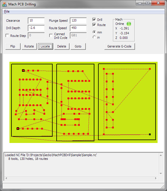
The fields on the application are...
| Field | Description |
| Clearance | This is the clearance height that the tool will be retracted to when traversing between points |
| Drill Depth | How deep to drill to. |
| Route Step | Not implemented. This allows for multiple cut levels when routing. |
| Plunge speed | The speed the drill bit is plunged into the work piece. The plunge distance is from Clearance to Drill Depth. |
| Route speed | The routing speed. |
| Canned Drill Cycle | When selected, uses a canned drill cycle, otherwise it uses a combination of G0,G1 commands. |
| Drill | When checked, generates GCode for drilling. |
| Route | When checked, generates Gcode for routing. |
| mm/in | Generates metric (mm) or imperial (in) GCode output. |
| Mach Online | When the light is Red, MachPCBDrill is not connected to Mach. When Green, MachPCBDrill is connected to Mach. |
| Mach X/Y/Z | Shows the current X/Y/Z coordinates of Mach3 |
| Flip | Used to match the mounted board to what is displayed. The flip button will flip the board over (mirror) |
| Rotate | Used to match the mounted board to what is displayed. The rotate button will rotate the board 90 degrees. |
| Locate | After the tool has been aligned over a hole using Mach, pressing the Locate button will remember the "real" coordinate. After 3 points have been located, GCode can be generated. A located point can be identified by the black outline around the red square. The currently selected hole is a black square. |
| Delete | Delete will forget a located hole. |
| Goto | After 3 holes have been located, select any hole on the board and select goto. This will tell Mach to move the tool to the hole. Used to double check everything is aligned. |
| Generate G-Code | This button generates the G-Code. A temporary file is created (using the system settings, so it should be in the TEMP directory), and automatically loaded into Mach. |
Procedure
- Mount your PCB on your machine. Theoretically, it can be at any angle (45°?), but be sensible and keep it to a multiple of 90°. It doesn't need to be accurate, that's what MachPCBDrill is for.
- Run Mach
- Run MachPCBMill. Ensure the Mach Online light is green. If it is not, it usually means there is something wrong with Mach's COM registration. Trying running Mach once as administrator.
- Load the NC file.
- Use the Flip and Rotate buttons so what you see in MachPCBMill is what you see on your machine's table.
- Next is the alignment phase. You need to pick 3 points to be used to align the board. Ideally you will pick points that make a large approximate right angle. The further the points are away from each other, the better.
- Start with the first point. Use Mach to jog the tool directly over the hole. In MachPCBDrill, make sure the point is selected, then hit the Locate button. Repeat for all 3 points
- When the 3 points have been located, pick another random point in MachPCBDrill and hit the Goto button. Mach will move to the tool to the hole. Confirm it is correctly aligned.
- Finally, hit the Generate G-Code button. The G-Code is created and loaded into Mach. You are ready to mill!
Known issues
- Only metric M48/METRIC,LZ NC files have ever been used. Worse, the files are generated by my own export program, so the metric NC files I use may be non-standard.
- I've only used metric G-Code output.
- The program only supports routing straight line segments. Arcs don't work, but it shouldn't be hard to convert them to line segments.
- The drilling height is from the Clearance height to the Drill Depth. This can make drilling really slow if the clearance height is high.
- There is no allowance for drill diameter. A large drill usually needs to be plunged slower and deeper (the V becomes significant)
- I don't particularly want to support this any more.
Sample
In the download package, there is a Sample directory, containing a sample PDF circuit, and matching NC drill file. These can be printed on paper and glued to some cardboard or wood to test the program.
Download
The source and binary is here ![]() .
.