Doorbell Extender
I'm quite often in the garage or the workshop, away from hearing distance of the doorbell chime, or just wearing ear protection. I really want one of these. However, the receiver only works on 110v. They don't look too complex, so, I'll make my own.
Transmitter
A wired doorbell is quite simple. A transformer (240v AC -> 9v AC) is connected to a switch and a solenoid. When the switch is closed (ie the doorbell button is pressed), the solenoid activates, striking a metal plate or two (ie the chime). All that is need then, is a transmitter that broadcasts when the button is pressed. This is shown below.
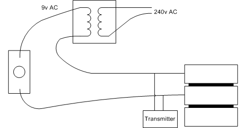
If transmitter is small enough, it can be placed inside the chime housing.
Design
The transmitter only receives power when the doorbell button is pressed. The transmitter must therefore charge up enough capacitance to keep broadcasting for a while. Apart from that, the circuit should be quite simple. I plan to use an ATtiny25 to send a serial stream of bytes to a wireless transmitter module. The transmitter module available from altronics runs on from 3v to 12v. The more voltage, the longer the range. The schematic is shown below.
![]()
The circuit uses a 7808 voltage regulator to provide 8v to the transmitter. Why 8v? Because I had a pile of them in my spare parts bin (no idea where I got them from though). Then another regulator is used to generate 3.3v for the the microcontroller. The circuit uses a transistor to level convert the 3.3v to 8v. I don't know if this is necessary - I'll find out when I try it.
The ATtiny25 doesn't have a UART, so the serial data stream will be generated in code - not a real issue as this is all it will do.
The data stream will be a string of bytes, something like "The doorbell has been pressed", along with a crc32 checksum to prevent falls rings.
Transmitter PCB
This is the first cut of the PCB. It is single sided, with mostly surface mount parts.
![]()
Receiver
I'm not sure how I'm going to implement the receiver yet. This is the list of requirements...
- Plugs into 240v power point. Ideally it is one solid unit, not a box and a cable or wall-wart
- Obviously repeats the doorbell sound
- Will the doorbell sound just be another chime doorbell, or a sampled sound, played into an amplifier and speaker?
- Must also flash a light, so I can see it rather than relying on hearing it.