UV Exposure Light Box
I'm just toying around with this idea at the moment. If I start using photo exposure PCB type production, I'm probably going to need a light box. I have tried using spray on photo-sensitive resist and exposure to the sun. It was a complete failure. Presensitised boards, and a light box seem the way to go. I haven't read much about this technique on the web, so I'm still a bit cautious.
Most commercial light boxes are very expensive. I think I should be able to put one together using a brief case, some UV CCFL tubes (or better still UV fluorescent), a μC, an LED display, a relay or two, a few switches, and a couple of pieces of glass.
Here's a couple of custom ones. ATM, Electronics Lab,
Features
- Double sided board support
- Electronic count down timer
- Safety micro switch to turn it of if someone opens it when on.
Implementation
This was just too good of a project to not do, so I jumped straight into it and built it.
The Light Source
I was originally planning to use some of the UV tubes available from the local Jaycar. They have UV and blacklight flourescents, UV LEDs, UV CCFLs, but not detailed specifications on the UV wavelength emitted - but most importantly me, they couldn't tell me whether they were suitable for UV exposure.
After a bit of web searching, I found mention of someone having success with the NEC UV lights. A bit more searching and I found them available from Kalex. Not only do they sell the tubes, but they sell UV Light Boxes, which I assume use these tubes. And they also sell Kinsten, and developer, so this seemed to be the right source.
They sell 3 tube sizes...
| Power | Diameter (mm) | Length (mm) | Fitting |
| 8 Watt | 15.5 | 287 | G8 |
| 15 Watt | 25.5 | 436 | G13 |
| 20 Watt | 32.5 | 588.5 | G13 |
I selected the 15 Watt size because it used a standard G13 fitting, available from my local hardware store. I had also picked up a dozen 15 Watt UV ballasts for $1.50 each from Rockby which matched perfectly. I know now that I could have got the G8 fittings from Middendorp. I could have also got electronic Ballasts that could drive 4 tubes, making the whole case smaller, but costing a lot more.
Box Construction
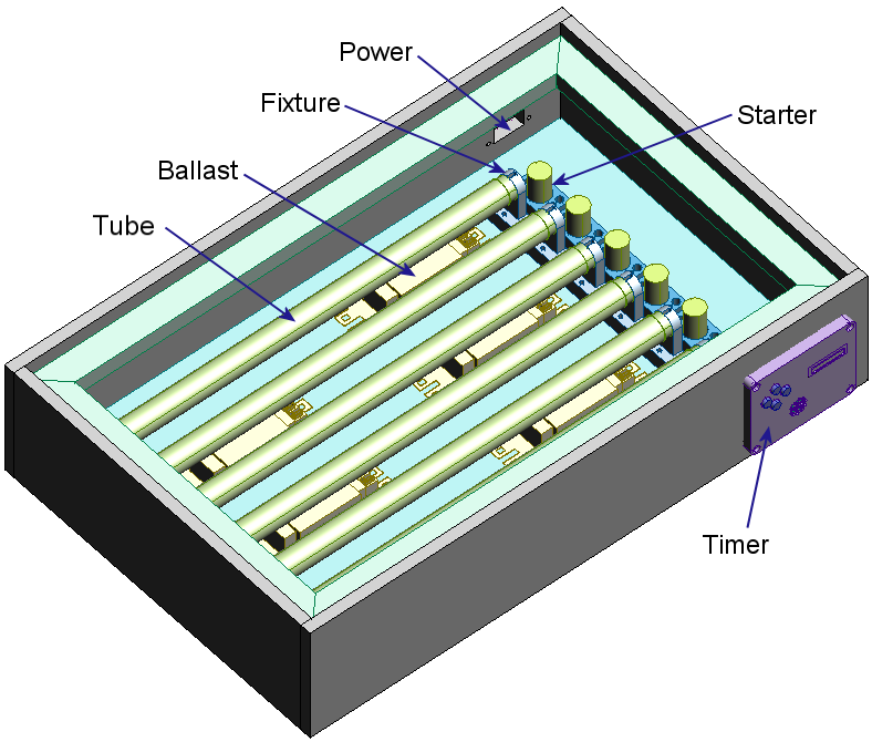
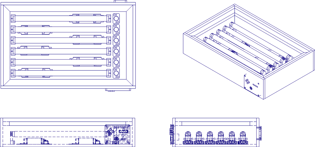
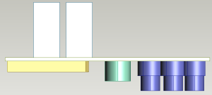
As I normally do, I obtained at least one of each components, measured them up and entered then into ProDesktop Express. Then I put together the design, a simple plywood box, with a lip around the edge to sit the glass. The only design parameter, apart from fitting everything in, was to ensure that the lights remained 5cm away from the circuit board being exposed.
Nothing really tricky here. Well it shouldn't have been, except that I nailed together the front face of the box upside down, so that the timer circuit was a bit too high, and ran into the ledge. It still worked though.
Timing Circuit
The timing circuit gave me the opportunity to use one of the 8 character 5x5 LED display units I got on special from Rockby. I got them for about $3 each - they are back to their regular prices of $32 - OUCH!
To drive the display I grabbed a AT90S2313 that I had lying around, a couple of 240V rated relays to switch the top and bottom banks of lights independently, and a buzzer to buzz.
Unfortunately I forgot to add the case open sensing switch to be able to turn off the lights if the box was opened. Another enhancement I would have added was a light detector or two to sense when they lights are on - the fluorescent lights can take a couple of seconds to light, so I would have liked to take that into account before starting the count down timer.
The circuit was pretty simple, as it usually is with a microcontroller.
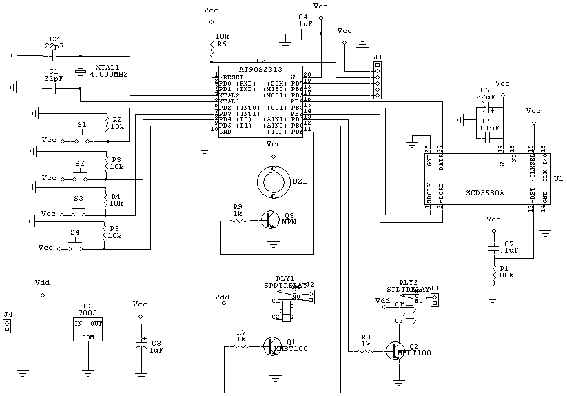
The circuit board was my first attempt at a double sided board. Not only were there tracks on both sides of the board, there components placed on both sides. This was done because the relays where big and chunky. It was also easier to have the power connector coming in from behind. The buzzer was a bit too tall and should have been on the back.
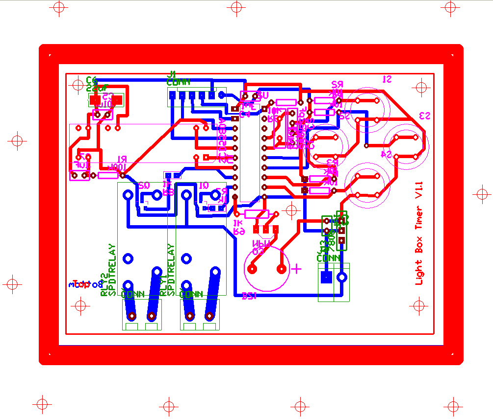
The cross hairs around the edge of the diagram are to help align the top and bottom TTF sheets when applying it to the blank PCB. It showed how crappy my laser printer is at producing accurate prints. The alignment was pretty poor, but not enough to cause problems.
The circuit is for version 1.1. I mucked up the pin outs for the SMD transistors underneath the relays. I get that wrong every time. The completed board used revision 1.0, with the through-hole equivalent transistor instead of the SMD one because it was easier to force in there.
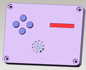
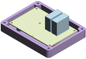
The board was mounted inside the lid of a Jaycar project box. The holes were milled out accurately, except that I stuffed up the positioning of the buzzer, and its sound holes, but it is not really visible from the outside.
Programming
Two count down timers, one for warm up and one for exposure, and a way to select bottom, top, or both sets of lights should not have been a difficult program to write. Squeezing it into 2k of ram, should also not have been to difficult, but it was. Maybe it was because it was written in C, or maybe it was because the LED display is a bit map device and I had to generate the font set. Regardless, it was a major drama trying to squeeze the code into the microcontroller.
To squeeze it in, I had to pack the fonts into a type bitmap structure. It went from...
Fixed Array of characters 32-127, 480 bytes, ...
| Row1 | Row2 | Row3 | Row4 | Row5 |
To an array of only the characters we needed, 33 of them, 198 bytes, ...
| Character ID | Row1 | Row2 | Row3 | Row4 | Row5 |
To a bit stuffed version, 132 bytes...
| Byte 1 | Byte 2 | Byte 3 | Byte 4 | ||||||||||||||||||||||||||||||||
|
|
|
|
The processing of this was much more time expensive, but seeing we are only ticking down once every second, it was not an issue.
I also had to scan the assembly output generated from the compiler. The C compiler did some strange things when converting between 8 and 16 bit, and between signed and unsigned. Often it would convert two 8 bit values to 16, add them, then convert them to 8. It took a lot of casting to "encourage" the compiler to do the right thing.
All the other processing was simple. The communications to the LED display was straight forward as described in the datasheet.
In the end, I had 20 instruction words free.
The Final Product (Part 1)
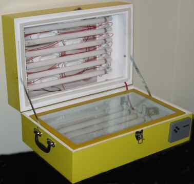
Here are some snaps of the completed bottom half of the exposure box.
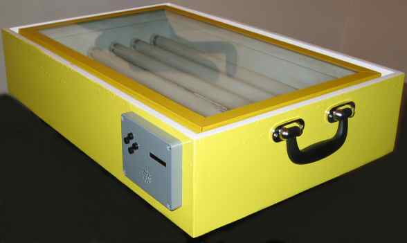
The box. Note the funky handle on the side. There are 2 pieces of glass on the box, with the edges protected with some cloth tape. Boards are exposed by sandwiching the image and board between the panes of glass. If you look carefully on the front of the box to the left you may see what looks like jpeg artifacts. They are actually runs in the paint. I thinned the paint down too much and applied too much when I sprayed it. Even though it had the consistency of honey, I should have used it as it was.
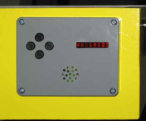
The timer control panel. The display reads "Wm 14:27" meaning it is running in warm-up mode, with 14 minutes 27 seconds still to go. I read on the internet the UV tubes need 15-20 minutes to warm up. The 4 buttons are used to activate the modes and set the time values.
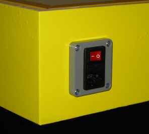
The power socket. This is a combination IEC socket/Fuse/Switch, mounted into a lid of small box, then screwed into the light box. It made a much safer and stronger mounting.
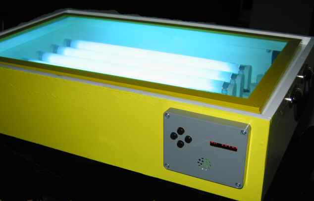
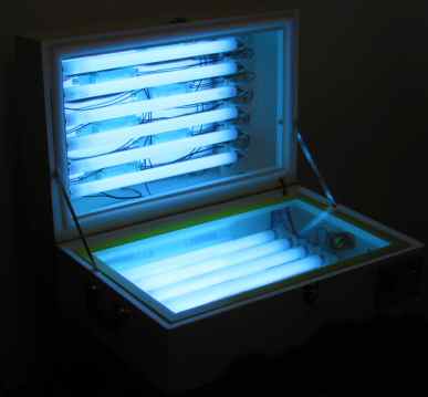
Action Shot. Behold the Ultra Violet glow.
Results
OK, so did it work?
I purchased a slab of supplies, some developer, a couple of double sided fiberglass boards, a couple of single sided Paper Phenolic boards. Paper Phenolic boards are cheap, so I'll use them to experiment with exposure timings. If things didn't work, I could always scrape of the Kinsten and use them as regular boards.
I made a test pattern that would fit on a 100mm x 150mm board. The pattern was repeated 6 times with the aim to expose each section for 30, 45, 60, 75, 90, and 105 seconds.
I printed this on Transparencies made for Laser Printers. It was not a very strong image. The blacks were a bit washed out.
I exposed this by manually watching the clock and sliding a piece of paper across the surface to limit the exposures. The results are shown below...
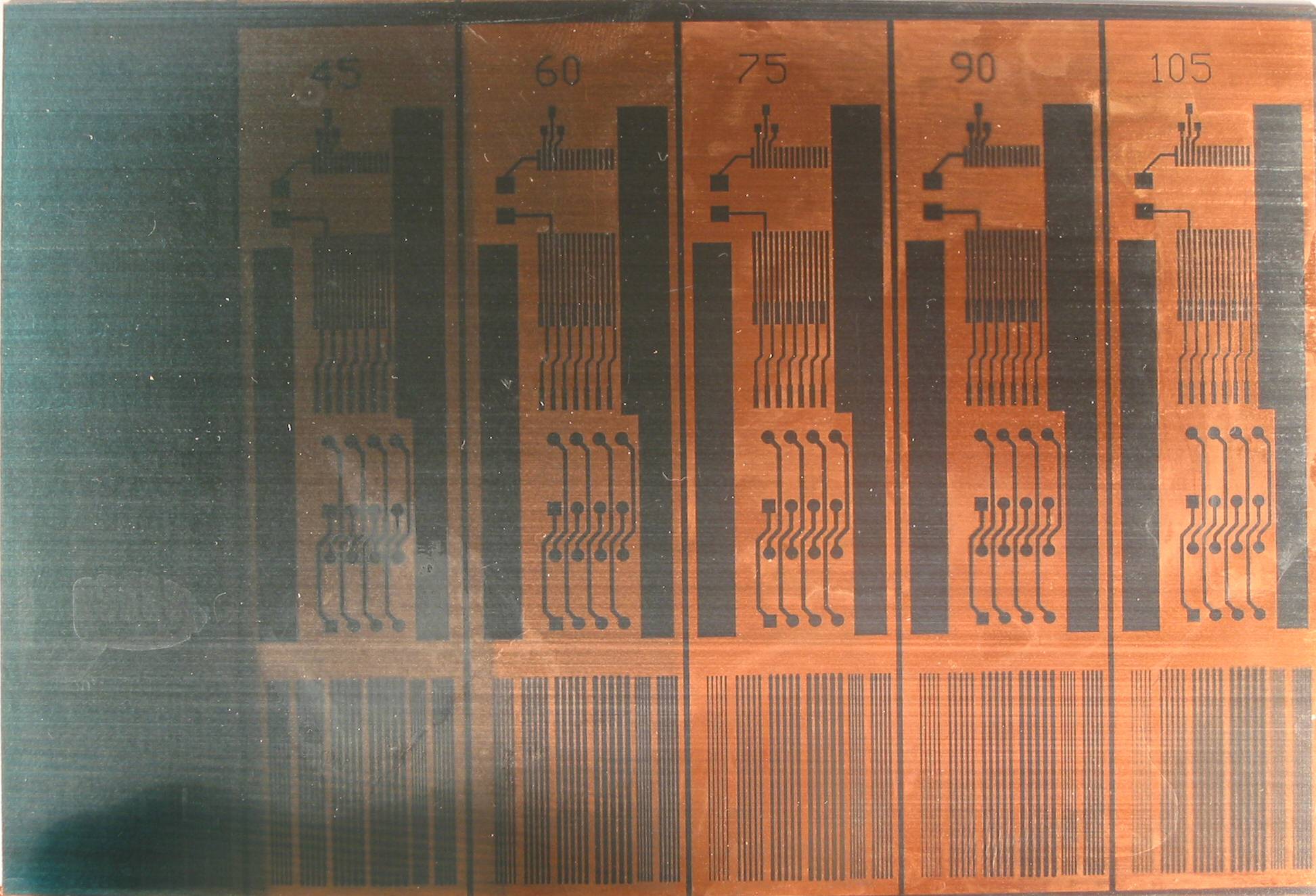
The picture is of pretty poor quality. Focusing is ok, but the lighting, and dirty circuit board make it look poor. As you can see, 30 seconds of exposure is only enough to show a general out line. 45 seconds starts to show the circuit. 60 is still a bit green. 75 is better, but the best results are at 90 and 105. If you look closely at the large image, you can see the finely space lines at the bottom are blurred in to 105 test. This is because everything gets knocked about as I moved the paper blocking exposure.
I repeated the test, with only half a board this time at 90 seconds and 105 seconds. Then I etched the boards. 90 seconds was the best. All traces came up sharply, no blur, and the large areas of copper remained solid. In the 105 second exposure, the large areas of copper started to become exposed and look like the transparency. Although this is a more accurate copy, 90 seconds gives a better contrast result. (Sorry no pictures - they were all crappy, out of focus and poorly lit).
Bottom line - this process is great. In the test exposures, the lines at the bottom are...
| Line Width (mils) | Separation (mils) |
| 10 | 10 |
| 15 | 10 |
| 20 | 10 |
| 25 | 10 |
| 10 | 5 |
| 15 | 5 |
and they all look fine. The 10 mil thick lines look a bit thin, but there were no signs of breaks that would occur with Toner methods. I think the thinnest I will use is 15mil thick, 5mil apart.
Phase 2
The next step is to make the top half. I've decided I'll put lights in the top too, to support double sided boards.
I still have 2 unused ports on the microcontroller, so I might add the open detection micro switch. That's if I can squeeze in the extra code.
Also, I purchased some LaserStar A4 print film from Computronics. They claim the blacks are blacker. I assume this means the toner sticks better. This stuff looks like drafting film, a translucent, white, plastic-like paper. I suspect exposure times will be different for this, so I'll need to do the exposure tests again.
Update: I now use Laser Film, A4 110MY, from GCC printers. A lot cheaper. I tried their toner enhancement spray but it doesn't work with my Xerox 240A printer. I'm told it uses a plastic toner, whereas the toner enhancement spray only works with carbon based toners. And for the record, I have seen the results of the toner spray. It completely blackens the blacks. GCC will send you samples so you can see for yourself.
Phase 2 Implementation
In the end, I just built the top half similarly to the bottom half. I didn't try to add the open detecting micro switch.
Again I had problems with the paint. Impatience led to runs in the paint. It is also taking forever to dry. Next time I spray paint timber I will try a 2 pack paint, if I can find some.
Here is a photo of the completed box. There is a piano hinge holding the two halves together, two card-table stays to hold it open and a case latch to keep it closed.
And of course, the action shot...