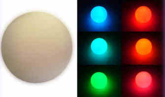
Orbee - the USB controlled glowing orb
Murray's functional requirements requested "a USB device you control by placing a file in a particular folder or something". Hmmm. Concise. And, not a bad idea. It is going to be similar to all those LED blinky kits you can buy, but this one will be USB controlled. Murray's idea is to use it to signal the end of a build (red=bad, green=good). Having a programmable interface means developers can use it as they wish, eg build status, late for a deadline, you have mail, lunch time etc.
So, here's how I built one from a cheap orb on ebay. I got a couple of these for $A4.99 each from ebay seller CostSaviour (search for globe).
Design
The best option was to build a USB device, because the device can also be powered by the bus. I prefer Atmel's 8 bit microcontrollers, so the obvious choice was the at90usbXXX family. Because this was such a simple project, I chose the at90usb162, an 8 bit microcontroller with 16k for program memory in a 32 pin TQFP package. (the at90usb82, with only 8k of flash would have been fine too). The cool thing about the Atmel USB microcontrollers is that they come pre-flashed with a boot-loader rom. To program them, you don't need an ISP or JTAG interface; you can just use the USB interface (unless you get it wrong).
A requirement for the device was ease of installation and programming. I did not want to write drivers for the device, and I wanted a simple API. Windows and Linux (and maybe MacOS) natively support HID (Human Interface Device - eg keyboards, mice, joysticks, etc) and CDC (Communications Device Class - eg serial ports). HID, however, requires more complex user mode code to be written to access the device. CDC, is simple - open the port and write to it. CDC was the selected interface.
While I was waiting for the parts to come from Digikey, and the orb to come from ebay, I experimented a bit with other methods of USB interfacing. There are a couple of examples of USB interfacing with simple microcontrollers, such as usbtiny, avr-usb/v-usb, and IgorPlugUSB. I got these working, but they had a couple of limitations. Firstly, they only run at low speed mode, 1Mbps, which isn't really a short coming for this project. Secondly, in order to interface to the device, you need to write your own drivers. I did try to implement a CDC device (actually I just built and tried to debug the samples) but I couldn't get it to run reliably.
I initially developed the code using an AT90USBKEY, Atmel's USB demo board. I built the application and got it to drive three LEDs, a Red, a Green and a Blue. I had to stop there because I didn't know how the orb worked, and how I was going to squeeze the electronics in.
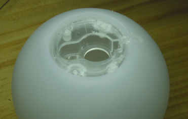
When the orb finally arrived, I could pull it apart and find out how much room I was going to have.
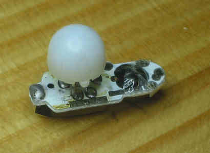
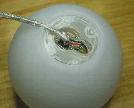
Above is a top view of the internal circuit board. It is small, about 11mm x 20mm. The black blob on the right is the controller semiconductor buried under a blob of black epoxy, wrapped in a layer of clear sticky tape. The large white blob on the left is the LED diffuser. Three 3mm LEDs are mounted to surface mount pads on board, under the diffuser. The pictures below show it better.
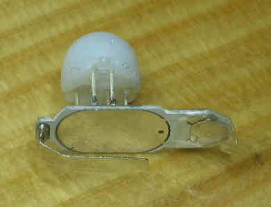
This is the bottom view. The large silver area is the battery positive contact area. There is a metal tab on the left that connects to the battery negative terminal. The orb uses 2, 3 volt lithium button cells. On the right is a small piece of spring steel held in position by sticky tape. This is the mode switch (switches the original orb from single colour modes, to colour cycling).
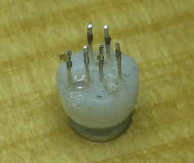
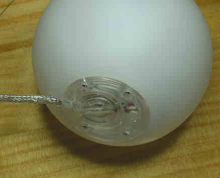
Here is a closer view of the 3 LEDs and the light diffuser.
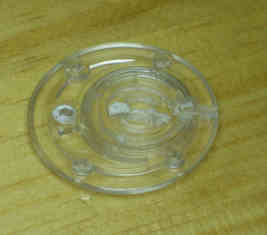
The base of the orb has an opening for the circuit board. It is covered by a plastic cover held on by four small screws, with a small cap to provide access to the batteries.
This is when the real drama started. How to squeeze the circuit board into the orb. My original design had what I thought was the bare minimum - microcontroller, USB connector, reset and HWB push buttons, crystal, surge suppressors, ISP connector. There was no way I was going fit all that on a board that would replace the original. So, my first design was a two part circuit. A larger circuit board close to the USB port, and a smaller one inside the orb. A small 4 wire cable connected the large board to the small board in the orb. This wire just connected to the LEDs. I wasn't happy with the way this design was heading, so I decided to start losing things.
First to go was the ISP (In-ciruit Serial Programming) interface. As mentioned above, the at90usbXXX range comes preloaded with the boot-loader flash. The first time the completed circuit is plugged into a USB port, Windows XP will notify you that an AT90USB162 DFU device has been detected. This is the USB boot loader rom. You can use Atmel's Flip application (available from www.atmel.com) to upload a new firmware.
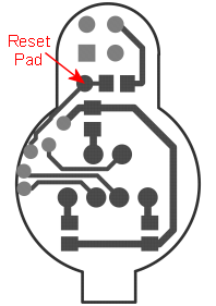
Next to go were the Reset and HWB push buttons. This is a risky omission because this is the back up way to access the boot loader firmware. If your firmware does not switch into boot loader mode when requested, you can push the reset button, push the HWB button, then release the Reset button, and the device will enter boot loader mode (assuming the bootloader hasn't been wiped). As my firmware can manually switch into boot loader mode, I thought this would be an acceptable risk. As a precaution, I added some exposed pads connected to the Reset and HWB pins on the microcontroller, so if I every got caught out, I could get back into boot loader mode by shorting the tabs to ground with a couple of scraps of wire. And lucky I did because I made a mistake in the firmware and couldn't get into the bootloader.
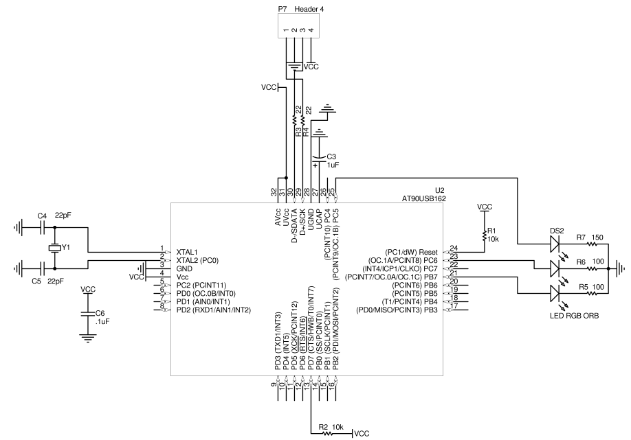
I also removed the USB connector, so the wires now connect directly to the board. I removed the surge suppressors - fingers crossed there is no static. And I needed to do some creative soldering and component placement to add the crystal. The circuit diagram and PCB is shown below. Note that the PCB pictures are about 3 times the actual size.
 |
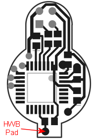 |
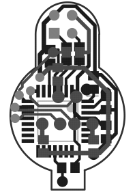 |
| Top | Bottom | Both |
Note that the PCB was home made, therefore there are no hidden vias and no plated through holes. It could be made smaller and through holes made for the crystal.
Implementation
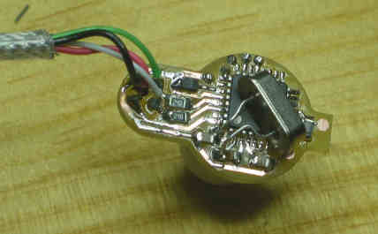
Below are some pictures of the completed boards. Note the soldering of the crystal. It is soldered directly to the SMD pads and then laid across the microcontroller. I didn't have any of the small cylinder type crystals in the 8MHz range, so that had to do.
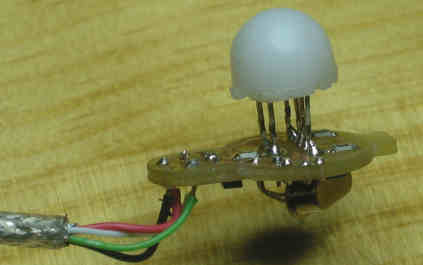
And finally, the assembly...
The PCB is a nice snug fit.
The USB cable is just over 3.5mm thick, so a 3.5mm hole was carefully drilled into the side of the orb's base to let the cable in.
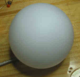
And finally, tada! A completed Orbee!
Firmware
The firmware for Orbee is built upon LUFA, the open source USB implementation for AVRs by Dean Camera. I basically took the USBtoSerial example, and made it into Orbee.
The firmware source is here ![]() .
The Orbee source is in Source/LUFA
090605/Demos/Device/Orbee. The rest is LUFA. Note that
there is a .INF file in the orbee directory. That is used in
Windows XP during installation. It basically tells windows to
use its own internal usb serial driver. Also note that Orbee
uses my USB PID/VID, so if you use the code for your own projects,
make sure you change them (in the .inf file and descriptors.c).
.
The Orbee source is in Source/LUFA
090605/Demos/Device/Orbee. The rest is LUFA. Note that
there is a .INF file in the orbee directory. That is used in
Windows XP during installation. It basically tells windows to
use its own internal usb serial driver. Also note that Orbee
uses my USB PID/VID, so if you use the code for your own projects,
make sure you change them (in the .inf file and descriptors.c).
The firmware processes the commands and then uses Timer1 to generate the PWM outputs on OC.1A, OC.1B and OC.1C. Theoretically, when all three LEDs are on, the globe should glow white, but it tends have a coloured tinge. I tried measuring the currents that the default orb generated. I got about 60mA using my multimeter, and 30mA using a 1Ohm resistor and a scope. Unfortunately, driving the LED directly from the microcontroller has a 20mA limit, so I couldn't get similar settings.
Interface
As mentioned above, the interface is via a serial port. You can use a terminal program to write to Orbee. Under Linux, the device appears in /dev, and can be written to by applications or scripts, for example...
echo CFF0000 > /dev/ttyACM0
Note - Orbee does not echo commands as they are entered. It does acknowledge a successful command with "OK".
Orbee has two commands...
1) BOOTLOADER - jumps into boot loader mode. Use Atmel's Flip to reprogram Orbee. Unless you are bug fixing or rewriting the protocol, you wont need this.
2) CRRGGBB[:time[:RRGGBB:[time...]]] <CarriageReturn>
The C... command is the only real command. It is a simple text
string that can be combined into confusing commands to get Orbee to
do things. A colour command can have 40 segments.
Command Syntax
| C | Start of a colour sequence command. It must be uppercase. |
| RRGGBB | Hexadecimal colour value, eg FF0000 is red, FFFFFF is white. |
| Time | The amount of time, in milliseconds to morph from this colour to the next. At the end of the sequence, the colours wrap to the beginning, so the last time is the time to morph back to the beginning. |
| CarriageReturn | commands are terminated with a carriage return (or new line). |
Examples…
| CFF0000 | Orbee is red |
| CFF0000:1000:00FF00:1000 | Start at red, morph to green over 1 second, morph back to red over 1 second. |
| CFF0000:500:FF0000:0:000000:500:000000:0 | Start at red, morph to red over 0.5 seconds (this means stay read for 1 second), morph to black over 0 seconds (instant change), stay black for 0.5 seconds. |
More Examples
| Red | CFF0000 |
| Colour cycle | C000000:2000:FF0000:2000:FFFF00:2000:00FF00:2000:00FFFF:2000:0000FF:2000:FF00FF:2000:FFFFFF:2000 |
| Strobing Police Lights | CFF0000:10:FF0000:0:000000:100:000000:0:FF0000:10:FF0000:0:000000:100:000000:400:000000:0:0000FF:10:0000FF:0:000000:100:000000:0:0000FF:10:0000FF:0:000000:100:000000:0 |
| Blink Red | CFF0000:500:FF0000:0:000000:500:000000:0 |
| Blink Green | C00FF00:500:00FF00:0:000000:500:000000:0 |
| Blink Blue | C0000FF:500:0000FF:0:000000:500:000000:0 |
| Blink White | CFfffff:500:Ffffff:0:000000:500:000000:0 |
| Blink Pink | CFf00ff:500:Ff00ff:0:000000:500:000000:0 |
| White/Red | CFFFFFF:500:FFFFFF:0:000000:500:000000:0:FF0000:500:FF0000:0:000000:500:000000:0 |