RGB Matrix
As part proof-of-concept, part first steps to building my Jumbotron and part something to do, I purchased the RGB LED Matrix from Sparkfun Electronics, pictured below...
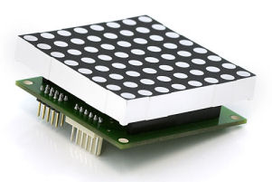
This is a 2 piece component. The top is an 8x8 matrix of RGB LEDs. Each LED has 4 leads: red, green, blue, and common. The leads are tied together to form a grid pattern. To display a pattern on the matrix, the LEDs must be lit one at a time at. They are normally only lit for a fraction of a second, then the next one is lit. To avoid flickering, the whole matrix needs to be lit at least 60 times a second. The schematic of the RGB Matrix is shown below...
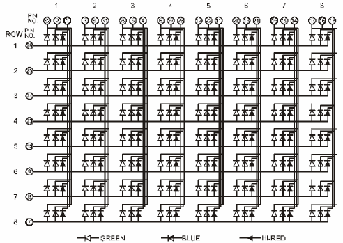
The bottom is sparkfun's own "backpack" circuit board used to drive the LED matrix. It uses a chain of shift registers to light up one row of LEDs at a time; that's 3 x 8 = 24 data bits at a time. The controller is an Atmega8. It bit bangs the data out via the IO ports to drive the shift register, and uses one IO port as a line select. It has an SPI serial input interface to display data.
The stock firmware only displays 8 colours (including black). I wanted to enhance the firmware to show the full RGB palette.
Display Multiplexing
Display multiplexing is used when you have to display a lot of LEDs using a minimum number of controller pins; the controller in this case being the microcontroller. LEDs are grouped together to have either a common anode or common cathode. By switching the common connection, different groups of LEDs can be lit alternatively. By repeating this quickly (more than 60 times a second) it gives the illusion of all groups being lit simultaneously. This is simulated in the animation below - note that a 1 represents the line being on, not a voltage or logic level, otherwise all the non-selected lines would be active. Here, 16 LEDs are driven using 8 lines. An 8x8 matrix of 64 LEDs can be driven with 16 lines. The RGB LED Matrix can be driven with 32 lines.
When cycling through the rows, it is important to turn off the row select before loading the row data. If this isn't done, ghosting between adjacent rows will occur. (this is a bug in the stock Sparkfun module).
PWM
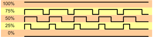
To display colours at different brightness levels, Pulse Width Modulation (PWM) is used to control the voltage to an LED. PWM turns the voltage on and off very quickly. By varying the percentage time on vs. off, the intensity can be varied. 100% on, and the LED will be at full brightness. 100% off, and the LED is off. 50% should be half brightness, but because we are relying on eye trickery, 50% isn't always full brightness.
PWM + Multiplexing
To get more colours out of the RGB matrix, Multiplexing and PWM are used. Ideally, we have modulation on each element. However, for the RGB matrix, this would require 24 PWM signals or external drivers. This a bit too much work, so software is used.
In order to produce PWM via multiplexing, we need to be able simulate the PWM cycles during our multiplexing update. Normally the multiplexing cycle is called once each period, but in the picture below, the multiplexing cycle is called 8 times effectively giving a PWM resolution of 12.5% (100/8).

Now the math, to see if we can fit it all in.
If we have 8 rows that we want to update at 60Hz, this means we update a row at 480Hz, or every 2.1ms, or with a 16MHz Atmega8, every 33,333 instruction cycles.
To update a single row of LEDs, we need to shift out a 24 bit value, select the row, then latch the data. The best I've been able to achieve is 252 instruction cycles, or 15.75μs. If all we did was update rows, we could do it 63,492 updates per second. We need to do 8 rows, 60 times a second, which means we can do 124 updates per row. This is more than enough μC power as we will only be using 64 intensity levels.
This means slightly more than half the capacity of the μC is used for updating the display, leaving the other half to read the SPI interface.
Data is 18bit RGB data, passed in 3 bytes, with the 2 most significant bits of each byte ignored. So, a full display of data is 8 * 8 * 3 = 192 bytes. To update the display at 60 frames per second, we need to be able to send 60*192 = 11520 bytes per second. This sets the minimum SPI bus speed to 11520 * 8 bits = 92.16kHz.
Given that a row update will take 15.75μs, and processing of the SPI will be done between between updates, limitations are put on the SPI bus speed. An SPI data byte must be retrieved before the next byte arrives and clobbers the one waiting in the buffer. 1/(15.75μs/8) gives 508kHz. This means the master SPI controller can't exceed 500kHz.
Implementation
The new firmware was written in assembler. The implementation is simple. The row painting is done off of the timer interrupt in the background. SPI is done inline in the main loop. That's pretty much it.
To tweak the performance, data buffers are aligned on 256 byte boundaries. That way we don't need to keep populating the H registers, or including them in the calculations. All variables are permanently stored in registers.
There are two buffers - the read buffer and the display buffer. Data is read from the SPI interface into the read buffer. When the read buffer is full, it is moved in to the display buffer. As it is copied, it is re-ordered to match the hardwire port and pin layout.
The line display interrupt routine uses the pixel colour intensity (0 to 63) as a counter compare value. The line display interrupt is called 64 times for each routine. The LED is only illuminated if the pixel value is less than the counter value.
The new firmware source is here ![]() .
.
Below is a picture of my enhanced version...
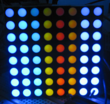
The photo is from an animated sequence cycling through the colours, varying the intensity from dull at the top, to bright at the bottom. The rows have brightness levels of 8, 16, 24, etc. There is not much difference in brightness for the values above 16.
Next
Next I need to work out how to get a better brightness spread. I don't know if it can be fixed in software. The shortest light period is 32.5μs. This seems too long to get a better selection of low brightness colours.
It may be able to be fixed by changing the values of the LED current limiting resistors. The stock values are 100Ω. Increasing the value will reduce the LED current and reduce the brightness.
The brightness could be better controlled if the update loop was shorter. One way is to use the μC's SPI hardware to shift bits out to the shift registers. Each byte could be shifted out at 8Mbps. There is some set up time to prepare the data, then 16 instruction cycles while the byte is shifted out. While the byte is being shifted out by the hardware, the next byte can be prepared. Unfortunately, the Sparkfun module isn't wire this way. Also, SPI interface is already used for loading the image to be displayed.
If the hardware is going to be changed, then it may be easier to find an AVR microcontroller better suited to driving RGB real colour. Either one that has 32+ free IO pins so each pin on the RGB module can be driven directly, or one that has 24 PWM outputs. Maybe this is a job for a Propellor?