T1 - Thomas version 1
Overview
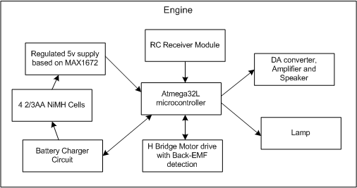
The following diagram shows the plan of attack...
![]()
As always, over-engineered, and the bar set way too high.
| Transmitter | |
| RC Transmitter Module | This is the transmitter module extracted from the remote control of the mini-RC car |
| 4 D NiMH Cells | The transmitter is designed to run on batteries. The batteries provide the power for the transmiter functions and enough power to charge the train when it docks with the transmitter, in the same way the mini-RC car does. |
| Battery Charger Circuit | So my nephew doesn't have to keep buying new batteries (he was 3 when I started this project), the batteries inside the transmitter will be chargable by plugging in a 12v power supply. The battery charger circuit is based on the Atmel AVR AppNote AVR450 |
| Throttle | The throttle is used to control speed and direction. It supports 3 forward speeds, stop and 3 reverse speeds. |
| Regulated 5v supply | To support running of different power sources (12v plug pack, or 4 NiMH cells - which may range from 4v to 6v) I chose the MAX1672 which accepts an input voltage range of 1.8v to 11v and outputs 5v (or 3v). An expensive chip though. |
| 9v step up supply | The train itself will have a NiMH power source which needs to be charged. The step up source provides 9v or so that will charge the train. This will be hidden in the track and a connection will be made when the train parks on top of it. |
| Atmega32 microcontroller | The core of the transmitter. It will be responsible for reading the throttle and button states and transmitting it to the train. The battery charger is also controlled by the microcontroller. |
| Buttons | There will be buttons for playing the whistle and ringing the bell. |
| Engine | |
| RC Receiver Module | This is the receiver module extracted from the mini-RC car |
| 4 2/3AA NiMH Cells | This is the power source of the train. The cells will fit nicely into the custom tender to hold the electronics, and provide enough power to last for an hour or two of driving. |
| Battery Charger Circuit | When the train docks the battery charger circuit will charge the internal NiMH batteries. This again is based on the Atmel AVR AppNote AVR450 |
| DA Converter, Amplifier and Speaker | These modules are used to make Thomas sounds. The bell and whistle sounds are controlled by the transmitter. The chugging sound is made when Thomas moves. The DA converter will be a simple R2R ladder. The amplifier will use an lm386 1/8 watt power amp. |
| Regulated 5v supply based on MAX1672 | Again, this chip was selected for its wide range of inputs. |
| H Bridge Motor drive with Back-EMF | A simple PWM FET H-Bridge is used to drive Thomas. In between PWM pulses, a voltage divider is used to measure the back-emf, and hence the motor speed. Then we can use a PID loop to keep the speed constant |
| Atmega32l microcontroller | The low power version of the atmega32 was chosen for the engine. |
| Lamp | The incandescent "grain of wheat" bulb was replaced with a high intensity LED. A light sensor will turn it on when it becomes dark, eg running at night, or through a tunnel. |
RC goodies
The RC transmitter from the mini-RC car has 4 switches - Forward, Reverse, Left, and Right. These buttons are paired together on 2 channels - Forward, Reverse on one, and Left, Right on the other.There are actually three states on each channel - Forward, Reverse, Stop and Left, Right, Straight. This gives 32 = 9 unique values that can be used to encode messages.
| Base 3 value | Transmitter Buttons | Buttons Decimal Value | Mapped Decimal | Mapped Binary Value |
|---|---|---|---|---|
| 00 | 0000 | 0 | 0 | 0000 |
| 01 | 0001 | 1 | 1 | 0001 |
| 02 | 0010 | 2 | 2 | 0010 |
| 10 | 0100 | 4 | 3 | 0011 |
| 11 | 0101 | 5 | 4 | 0100 |
| 12 | 0110 | 6 | 5 | 0101 |
| 20 | 1000 | 8 | 6 | 0110 |
| 21 | 1001 | 9 | 7 | 0111 |
| 22 | 1010 | 10 | 8 | 1000 |
The table below shows how these will be used to control Thomas.
| 0 | Stop | Always sent |
| 1 | Set Speed =1 | Always sent |
| 2 | Set Speed =2 | Always sent |
| 3 | Set Speed =3 | Always sent |
| 4 | Set Speed =-1 | Always sent |
| 5 | Set Speed =-2 | Always sent |
| 6 | Set Speed =-3 | Always sent |
| 7 | Button 1 | Momentary |
| 8 | Button 2 | Momentary |
Because of the limitations of the transmitting states, button presses are sent as momentary command, ie for 1 second, then revert back to a speed command. During this time, the speed is kept constant.
Audio
Thomas has to make sound - chugging sounds as he moves, and bells and whistles generated by the operator. This proved a challenge to fit about 100k of audio samples into an atmega32 which has 32k of program RAM, 2k of SRAM and 1k of EEPROM
To make this possible, I used ADPCM audio compression. This got the sound files down to about 16k, which were converted into C header files and included in the project. This put the audio data in program memory space. Audio samples were found on the internet somewhere. Goldwave was used to manipulate the sounds and convert the format.
The decoding software was taken from the open source SDL library. I initially started with C code, then optimised it, but I was not able to get it working fast enough, especially when trying to play 3 sounds simultaneously - a chug, a bell, and a whistle. So the C code was converted to assembler. The source for this is available here. (Not the nicest code as it was made to work then discarded in T2. It is also optimised to use my data structures.)
So what was the audio quality like? It sounded OK for a dinky toy, but I wanted better sound. This will need to be improved in the next version.
Motor Control
Control of the motor using PWM was quite simple. Just a FET H-Bridge. More on this in T2. It was trying to keep the speed constant that was tricky.
My first attempts at motor control were to use some from of feedback encoder on the motor. I created a plastic disk with two small pieces of metal embedded on the outer edge. This was mounted on motor shaft and a hall effect sensor mounted on the motor. This proved to be very bulky and very sensitive to position.
Then I tried putting a black and white striped disk on the shaft and used a hamamatsu photoreflector (bought from Acroname) to detect the motion. After some tweaking of the PID loop, I managed to get this work. Still bulky, but a first step. (sorry, no pictures)
I had read a lot on the internet about back-emf sensing and using this to determine the speed of the motor. This is what I settled on for the speed control. More details in T2.
Limitations, Issues, Problems
This page is being produced 2-3 years after I initially started so many of the dramas are not documented. The battery charger, and the PWM control caused the most grief and forced the project to be shelved numerous times. None of that is detailed here as other design issues arose...
- Now that my nephew has a sister, I'll need to make a second, maybe third, but the mini-RC cars only support 2 frequencies
- The transmitter is too big and bulky to have multiple
- 3 Forward/Reverse speeds are not enough
- Another button is need to manually switch the lights
- Sound quality is awful
T1 had reached a dead end, so it was time to redesign and start T2.