Moisture Sensor Prototype
The Sensor
For the prototype I decided to make my own sensors rather than buy them. If my simple blocks work, I can invest in something better later.
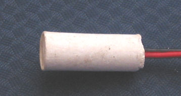
The only tricky part here was finding a suitable mould to cast the sensor. I had some small plastic containers used to contain bearings. They are about 20mm diameter, 70mm long. These set into a nice cylinder, but I couldn't get them out without destroying the mould (I though plaster shrank as it set). That would do for the prototype. My home made gypsum moisture sensor is shown below.
Electronics
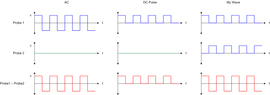
All the references I read said the resistance measurement circuit should use an AC signal. Some circuits only used a DC pulse. I decided to go half way. By alternating the voltage on both ends of the probe, I could get a relative AC signal across the probe. So, although the signal doesn't swing to a negative value relative to ground, the probe will see an alternating signal. Hopefully this will prevent electrolysis from forming on the electrodes. I am a little concerned that the probe will be buried in the ground which is at ground potential may have an effect. All my testing was done with pot plants.
The diagram below shows the different waveforms. Probes usually have one leg tied to ground and the other leg is excited with a signal. My version excites both legs...
The circuit to implement this is shown below. I used an Atmega32l, just because there was one already plugged into my bread board.
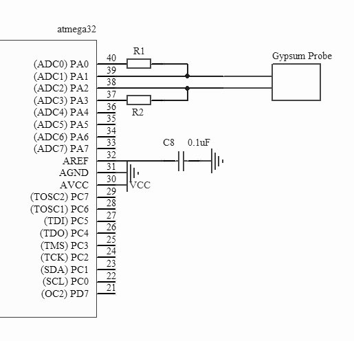
In the circuit, 4 micro controller pins are used to measure the probe resistance. PA0 and PA3 are used as digital outputs to produce the AC waveform; these can be moved to another port if the analog inputs are required. PA1 and PA2 are used as analog inputs.
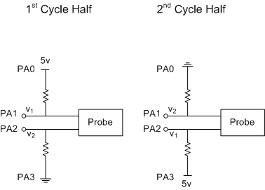
The resistance is measured in a loop, repeated 8 times and then averaged. Each loop, performs one half of a wave cycle.
During the first half of the cycle, PA0 is set high and PA3 is set low. Then the voltage at PA1 is read 8 times and averaged, v1. Then PA2 is read and averaged, v2. The difference between the two values is the voltage drop, which is proportional to the resistance. In the 2nd cycle, the voltages are reversed, and the order reading is reversed.
The source for the prototype is here. Note that there is ADC interrupt code, but that is not used (or working). The function of interest is MoistureSample().
The resistance of a gypsum block will be between 500 Ohms, and 30k Ohms (I'm not sure where I got these numbers, either on the internet, or possibly measured). A suitable value for R1 and R2 need to be select. I did this empirically, by plugging in 3 different values and measuring them. My original test placed the sensor in my African Violet test pot plant, but after 3 days, there was barely any movement. After a mild panic, I removed the sensor and devised a different test.
To provide better test repeatability, I placed the sensor in a cup of water for 10 minutes, then removed it and let it dry out. The prototype software took a sample every 5 minutes and echoed the raw Analog to Digital Converter value on the UART. This was then record by a PC and plotted vs time. This was repeated for 3 different resistor values, 470, 1.1k, and 10k. The results are shown below...
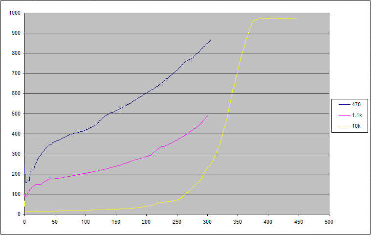
The Y axis shows the 10bit sample value, 0-1024, and the X axis shows the number of 5 minute periods; the 10k test ran for 450, 5 minute periods, or 37 hours.
The truncated graphs are due to, 1, my impatience, and 2, the USB port dying all the time (I was using a USB <-> Serial device). From this I decided to use 1k resistors. (I'm not sure why, as 470 ohm looks more linear).
Conclusion
From this, it looks like it should work. I'm not concerned about calibrating the values correctly. Over time, I should be able find a value which is moist enough, and then target that. The only tricky bit will be making the sensors similar. More on that when I come to it.