Garden Watering System - Phase 2
Issues
Size does matter
220 litres just doesn't cut it when watering a garden in an Australian summer. I rationed out 50 litres, twice a week. That gave me 2 weeks of watering between rains, but when it doesn't rain for 4 weeks, well I need a bigger tank. I have lots of room in the front yard, (compared to the back), but I still want the tank to be discrete, hidden behind the bushes. So on the shopping list for the front yard will be a tank of about 600 litres and low profile, about 1 meter high.
The backyard is a little trickier. My backyard is 1.3 meters wide, with a 0.9 meter wide path running up the middle. That leaves 20cm of garden on each side, and no room for a commercial tank, the narrowest of which are 600mm. I need a tank that is about 30cm deep (I can sacrifice some of the path), and 80cm wide (that's the biggest gap at the top of the garden). Sounds like I'm going to have to build my own (Yes! Woo! Hoo! Fibreglass! Woo! Hoo!)
So what did I use for the backyard proof of concept? Don't ask.
Diverters
As discussed in Phase 1, the water diverters need a bit of work. The nylex one appeared to work well, although it's hard to tell when you are only filling 25 litres. The Rain Tap, on the other hand, was constantly clogging up. That's the real reason I had a 4 week drought; it rained, but nothing went into the tank.
Phase 3 will directly pipe the water from the down pipe into the tank. With screens over the inlets, hopefully this will keep the muck out. If not, look out phase 4, where I'll need to research first flush devices.
Overflow
The complex plumbing to implement overflow was overkill and not necessary. Overflow management will be handled by the controller. The tank overflow will go back into the storm water system if the garden can't water fast enough.
Only one water level switch will be used; a high water mark switch. This may cause the valve to switch on and off a lot. Time will tell.
FETs
The FETs used in version one were not capable of handling the current the drawn by the valve. To solve this problem, I used a relay instead. I'm still a little scared of FETs. They should be simple to use replacement for transistors, but I've had too many unexplained failures. Maybe another project.
Temperature Sensor
This has already been mentioned. The temperature sensor must go OUTSIDE the box.
Crystals
Not the new age crazy type. The microcontroller in phase 1 used the internal RC oscillator to generate the system clock, but that is effected by temperature. This can cause problems with the timing of the UART. Although I didn't see any symptoms, a crystal will be used to maintain an accurate clock.
Solar Power
Yep! We're going green. The plan is to get a solar panel, 15-20 Watts, a regulator, and a SLA battery to provide the juice for the system. It needs to be able to open 2 valves at 2 Amps, twice a week for about an hour. That's about 8Ah per week. Hopefully the sun will shine enough to charge it.
Depth Sensor
The phase 1 system had no way of knowing how much water was left in the tank. Phase 3 will use ultrasonic distance sensors to measure the depth, and hence the volume.
Each tank will have one of these installed...
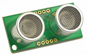
It's the Devantech SRF05/04 ultrasonic range finder. I got mine from Acroname Robotics.
These devices work by generating a 40kHz sound pulse, then waiting to hear the echo of the sound reflected off an object. The time taken to receive an echo can then be used to determine the distance, given that sound travels at approximately 340 meter per second. Multiply this by the cross-sectional surface area of the tank and we get the volume. Well almost.
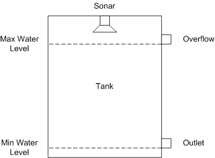
The picture below shows the set up. When the water is at its lowest, ie the longest sonar distance, the tank is empty. When the tank is full, the sonar measurement is at its lowest. Therefore the depth will be...
Min Water Level Length - Max Water Level Length - Measured Distance.
Bluetooth Modem
A really big :( here. I was hoping that this would work. A bluetooth garden sounds so cool. But it was not to be.
The problems are all on the PC side.
Firstly the range. My computer, and bluetooth dongle, are about 4 meters away from the tank. With a stock 10 meter range bluetooth dongle, it doesn't detect it. Putting the dongle on my laptop and sitting by the window will allow me to sometimes connect. The signal needs to pass through a single brick wall, and possible 50cm of water, depending on the dongle position. This is just too much for the dongle. So I upgrade to a 100 meter range dongle.
Well, a 100 meter range dongle was not much better. To get it to work reliably, I had to use a USB extension cable to to move it to closer to the tank. Finally some success. (The 100 meter bluetooth dongle was an ebay special. I wonder if it was really what it was labelled as?)
The next problem was the bluetooth drivers. The 10m dongle was a BlueSoleil. While developing the controller and PC software on my desk, I didn't have any problems. (Except for some magic CTS checking to determine if the connection was still up). Of course, I couldn't use this as the range wasn't good enough. The no name brand 100m dongle had the worst software I have ever seen (actually, most of the ebay special hardware has comparable quality software). Every time the blue tooth connection was dropped, the computer would play the "device disconnect" sound a dozen time - G-Dunk, G-Dunk,G-Dunk,G-Dunk,G-Dunk,G-Dunk..., and when it reconnected, G-Dink,G-Dink,G-Dink,G-Dink,G-Dink. There was no way to tell with their software if the other end was connected.
Luckily, the built in Windows XP bluetooth drivers supported the device. The only problem is that after a couple of reboots, the drivers would fail to reconnect to the bluetooth device. This would mean I would have to go into the bluetooth configuration and find the device again. That would also screw up the COM port assignment and I'd have to reconfigure the water service applications.
So good-bye Blue Smirf, hello RF Modem. This will be the replacement...
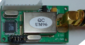
This is a 433MHz RF Modem, again from the good folks at Sparkfun Electronics. It has a range of 500 meters, and communicates at 9600 baud. It uses 30mA at 5v, and can be configured to use one of 8 different channels. And it is even more compact than the bluetooth module. It is similar to the bluetooth module, in that you just connect it up to the microcontroller UART. It seems to require a Reset pulse at start up.
Oh, and it comes with an antenna.
Oh, and it doesn't need a dongle, but you need a second one for it to talk to, so to use this I'll to make a transmitter; probably USB to RF Modem adaptor.
Moisture Sensor
How could I have entered phase 1 without even considering a soil moisture sensor. Well, we have phase 2 and 3 to fix that.
This took a fair bit of internet research to determine the feasibility. Firstly there are the different types: Tensiometric, Resistance, Heat Dissapation, Psychometric, Capacitance and probably more. Resistance was the only one that didn't sound to hard, so I continued researching.
Resistance moisture sensing works by measuring the resistance between two electrodes. I have seen this done with two electrodes plunged directly into the soil, but I'm not sure if these really measure resistance. Most probes have two electrodes embedded in gypsum (aka Plaster of Paris) or a composite. There is a chemical reaction between the gypsum and the water that effects the resistance. I've seen gypsum blocks for $10, and composites blocks for $120. Gypsum will dissolve in the ground and will only have a life of 1-5 years. Composites can last up to 10 years.
The resistance is measured by applying a voltage across the electrodes and measuring the voltage drop. This process is complicated by electrolysis occurring on the electrodes when a DC voltage is applied. Therefore an AC voltage should be used.
So, enough with the research, time to prototype. (hint: click the link)