Transmitter
During the phase 2 analysis, I decided to ditch bluetooth as my wireless communications method and use the wireless modems available from Sparkfun Electronics. With bluetooth, I use a bluetooth module in the controller, and use a standard dongle on the PC side. With the wireless modems, I need to use them in pairs: a transmitter and a receiver.
Design
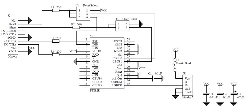
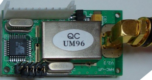
The RF Modem has a TTL serial interface (0-5v) and an RS232 level serial interface (±15v), so a standard serial port, or USB to serial converter would work. However, it also needs 5v, so I decided to cobble together my own USB interface and put it in a nice box. That way the transmitter could be powered by the USB bus.
The schematic is shown below.
I am using a FT232R from FTDI chip for my USB to serial interface. This is the latest generation of their chip. It includes 4 general purpose IOs, and on chip eeprom which can be updated using their MProg software.
The circuit could have been a bit more simple, unfortunately there were a few unknowns. Firstly, the documentation for the RF Modem was unclear whether the logic signals where 3v or 5v, so 200Ω resistors were placed inline.
Next, it was unclear from the documentation, whether the Sleep and Reset signals are required or optional, or if the modem needed to go through a reset sequence on power up. To allow for flexibility, the Reset and Sleep signals where wired to a jumper block to give them options...
- The Sleep signal could be switched to
- Ground, meaning always off.
- CBUS1, General Purpose IO 1, so the sleep line can programmatically changed, either by code on the PC, or by mapping a function to the pin.
- The Reset signal could be switched to
- Vcc, to keep the modem always on,
- CBUS0, General Purpose IO 0, so the reset line can programmatically changed, either by code on the PC, or by mapping a function to the pin.
- ~DTR, Data Terminal Ready, which is asserted when PC opens the serial port and is ready to send data.
The ferrite bead was added because it was recommended in the FT232R data sheet.
Construction
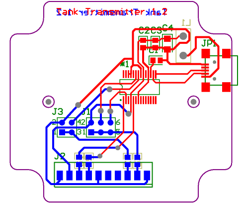
The circuit board for the transmitter is shown below.
The irregular board shape is so it can fit inside a small box, 65 x 60 x 40mm Sealed IP65 ABS Box, #H0300, from Altronics. The RF Modem is mounted on the lid. These are shown below.
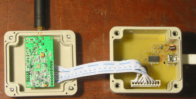
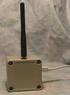
There were a couple of issues with the first transmitter. Firstly, the connector on the PCB for the RF Modem actually gets in the way of the RF Modem and the box can't be closed properly. To fix this, the connector will be removed, and the cable to the RF Modem will be soldered directly. There is a connector on the RF Modem, so it can still be disconnected.
The other problem was wiring the TX/RX. I got them the wrong way; connecting RX to RX and TX and TX is incorrect. Because the device is a modem, RX goes to TX and TX goes to RX. Obvious now that I think about it.
Configuration
Using the jumpers, I configured sleep to be always off (set to gnd), and I connected Reset to ~DTR. This means that when I connect to the modem from the PC using terminal software, the DTR line is activated and the modem is enabled. Unfortunately, the FT232R outputs the inverted DTR signal, but this is not a problem, because it can be inverted permanently using the MProg software. While I was there, I also gave the device a better name, which pops up when the device is inserted.
Using terminal software like Windows HyperTerminal works fine, as it automatically asserts DTR. When using my own software, I need to explicitly assert DTR when connecting, and then wait approximately 200ms for the modem to reset before I can send data.
