Garden Watering System - Phase 4 - Ongoing Maintenance and tweaking
I must have been dreaming if I thought everything was going to work right the first time.
26 March 2008 - Replace the filter
After a heavy overnight rain, the backyard tank was less than 1/4 full. The leaf catcher/filter clogged up straight away and hardly any water was captured.
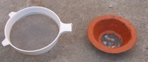
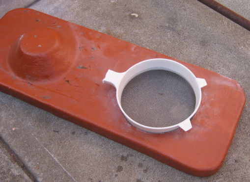
The small flat surfaced of the filter needs to be more like a kitchen flour sifter. So that is what I used. I cut off the handle, and made the hole in the tank lid bigger. Here are the before and after shots.
27 March 2008 - Panic! The Dam is going to burst!
 |
 |
| Before: Pretty tank with no water in it. | After: Full tank, ready to burst. |
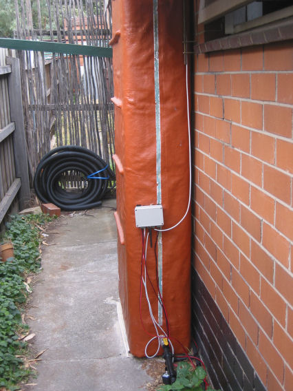
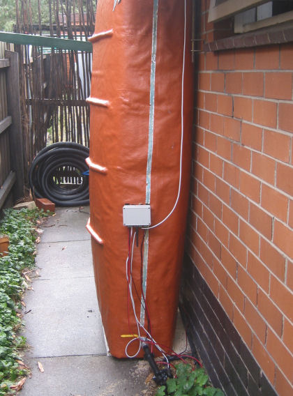
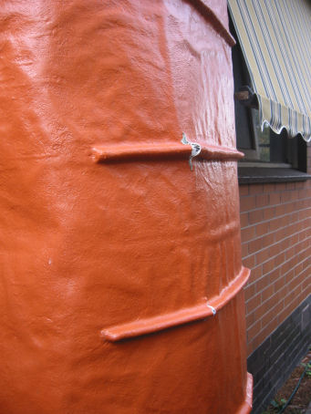
The bulging belly is obvious. Also notice at the bottom how it has pushed away from the wall. Hopefully it hasn't pushed the bricks in.
Here's a shot from the other side, showing the cracked "stiffeners".
And here's a close up of one of the cracks.
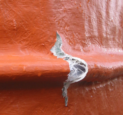
Surprisingly though, it is still holding the water, thanks to the water proofing goop.
Back to the drawing board. Maybe I should try to calculate the strength of the GRP next time. And use metal stiffeners. And put rods through the body of the tank to stop the expansion. Phase 5?
I need to keep an eye on it. If it does start to leak, a temporary work around is to lower the overflow hole so the tank can't fill right up.
29 March 2008 - Tank Repairs
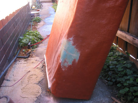
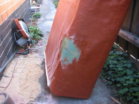
Unfortunately, I discovered a leak. It was a bit much to expect no leaks given the extent of the warping of the tank. On one of the edges near the bottom a crack appeared. It probably leaked here because it was so difficult to get the waterproofing goop down to that end of the tank, and into the edges. The paint was taken off, and a few layers of GRP were placed over it. Pictures below. The one on the right is the repaired crack. It is a bit hard to tell because the GRP is pretty translucent.
 |  |
While I was in repair mode, I thought I'd address the bulging problem. I created 4 steel braces to try and hold the tank shape. Pictures below.
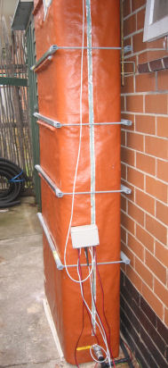 | 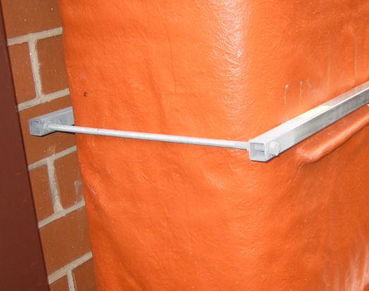 |
The braces are made from 20mm x 1.6 galvanised steel box section. 8mm galvanised threaded rod and nuts hold them together. The nut and rod on the brace against the wall is weld to the steel so it doesn't come lose when tightening.
Now I wait for the rain to see if it holds.
7 April 2008 - Re-jig the Depth Sensor
While browsing the robot electronics forums, I came across an article that described using the SRF02 single transducer sonar range finder with a piece of garden hose as a robot bump sensor. The garden hose acts as a wave guide for the sound, and only returns a sonar blip if the sound reaches the end of the hose, or if the hose is squeezed. This method will also detect water in the hose. Eureka!
I just happened to have an SRF02 lying around. See the photo below. I needed another sonar for the front tank, so I purchased an SRF05 (SRF04 replacement model), and while I was shopping I grabbed the SRF02 as well.
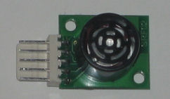
As you can see from the photo, the SRF02 on has one sonar transducer. The same transducer is used for transmitting and receiving the sonar pulse. This works great, guiding the pulse down a hose, but it does limit the close range sensing. When the pulse fires, there is mechanical ringing that must dissipate before the reflection can be measured. Having to wait a short amount of time stops being able to measure pulses that return while the ringing dissipates. This may cause problems when the tank is full. I'll find out when the tank fills.
This sonar module has an I2C interface. The Atmega88 microcontroller that is used in this project has built in I2C support (TWI in Atmel speak), but those IO pins were already spoken for. So the I2C interfacing was done using the existing hardware, and the I2C protocol implemented in software. It was based heavily on the code on the robot electronics site.
A garden hose is too flexible to be used to measure the depth of tank - that is, it may bend or curl up and give an incorrect reading. So I used a length of 20mm electrical conduit. The sonar is physically forced into the end of the tube. The end had to be machined to place the sensor correctly. With this diameter tube, the sonar was very sensitive to misalignment. The end was bored, and the sensor forced in. This shown below.
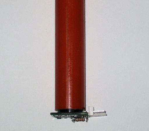
The colours are completely wrong in the last photo. The plastic tube looks red, but should be a bright orange.
To protect the sonar from moisture, the module was "potted" in epoxy. I hadn't done this before, and there was a serious risk it wouldn't work, but what the heck. I used 5 minute araldite epoxy, and covered the electrical components. This is shown below.
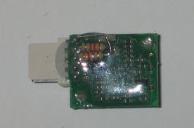
After the epoxy had set, I gave it a quick test. It all seemed to work fine. Note the two resistors in the photo above. These are the I2C pull-up resistors. It was easier to modify them on the sensor rather than the main board because I will probably use the SRF04 original sensor on the front tank.
The tube and sonar module were installed in the tank. This was painless. The picture below shows the top part of the tube. The tube is only attached at the top of the tank. I don't think it is buoyant enough to lift when the tank fills.
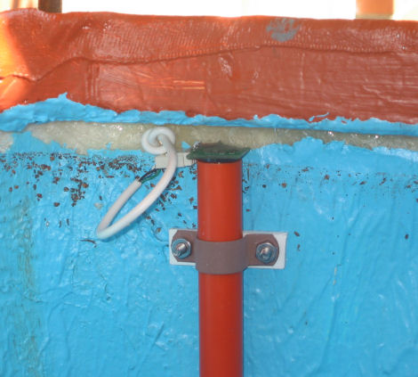
The current tank readings say 167. This is 167cm from the top to the water level. It is currently working amazingly well. Next, I need to see how it performs with a full tank, ie will the sonar measure correctly when the water is close to it.
I am also going to monitor how the distance varies by temperature. The equation for the speed of sound in dry air is...
speed of sound = 331.4 + 0.6*Tc m/s, where Tc = temperature in CelsiusThe temperature will vary from about 0C to 40C through out the year, varying the speed of sound from about 330 to 355, or about a 7.5% variation. If the tank volume moves around, I'll try to factor in temperature.