Digital Read Out
Digital read out for the Mill/Drill.
I already have the linear encoder strip, and the encoder sensor from US Digital. I just need to put it together and attach to the Mill/Drill. Oh, and all the electronics.
Components
There are 2 main parts to the DRO: the encoders and display.
Encoder
For the encoder, I am using linear strips and encoders from US Digital. I have 2 strips for the X and Y axis. Z will come later. The strips and encoder modules are 500 CPI, and with quadrature encoding, this gives 2000 CPI. High resolution, but a bit annoying that there is no metric strips with that resolution.
Now the tricky bit. It took more than 6 months before I actually started working on the mounting for the linear strips and encoders. I kept trying a design, wasn't happy with it, then shelve the project. I got inspired again when the Shumatec group did a bulk buy of strips and came up with the following design for the Y-Axis.
I've seen a few different layouts for encoder mounts. Most have a similar external rectangular sleeve with a runner, but use a slot running the length of the tube to fix the runner to the table. I will use this style for the X-Axis, but it was unsuitable for the Y-Axis because it would need to be mounted upside down, exposing the slot to muck coming off the mill.
![]()
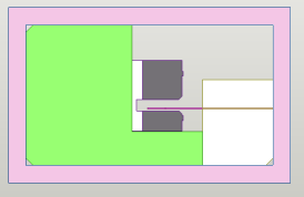
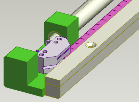
I saw this design, using a rod to push the runner on the internet. This will be great for the Z-Axis, and should work for the Y-Axis too.
The green item is a block of Polypropylene (I think). I started its life as a plastic chopping board but was then melted into a long bar and machined to make the runner The encoder module is mounted on the green runner precisely relative to the encoder strip. The encoder strip (hot pink) is mounted between to pieces of aluminium. The push rod is a piece of 10mm diameter, 1.6mm wall aluminium.
I made lots of mistakes building this first version. Most of the dimensions of the machined parts were off. The hole in the runner to hold the tube was not parallel to the boxing. I'll need to be more careful next time. And that's not a maybe; the first version MUST be redone. When ordering the linear strips, I forgot to specify the index marks. Instead, I will put limit switches on the next version. I also discovered I can thread the round tube, so in the next version, this is how I will connected it to the runner.
Display
The layout of my display is heavily based on the Shumatech design and the Easson design. The Shumatech DRO is a popular DIY DRO. Easson is a brand that my local machinery shop sells.
Rockby head some 7x5 LED dot matrix displays on special for 80 cents each. I couldn't resist and grabbed 100 of them. Although they are going to be tricky to drive, they will form the basis of the display. I could have used regular 7 segment LEDs, but where's the fun in that?
I broke the design up into 4 components: the main controller, key pad, indicator lights, and of course, the display. A block layout is shown below...
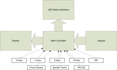
Like most of my projects, the Main Controller board has the micro controller and lots of plugs and sockets. I had a couple of Atmega64s lying around so I used one for the main contoller. This chip has 53 I/O pins, so I over-engineered the board to support...
- X-Axis input (A/B/I quadrature inputs, Min/Max limit switches)
- Y-Axis input (ditto)
- Z-Axis input (ditto)
- R-Axis input (ditto) - this will be for the rotary table.
- Touch sensor for edge finding.
- Spindle tacho for monitoring the spindle speed (and calculating SFM cutter speeds)
- ISP - In-circuit serial programming port (which is also used for the indicator lights)
- RS-232 for debugging
- Keypad - for 6x6 key matrix
- Display - uses 11 I/O lines to provide an LCD like interface to the display.
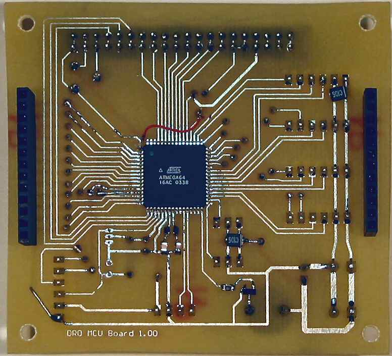
Here is a couple of shots of the main controller board.
 |
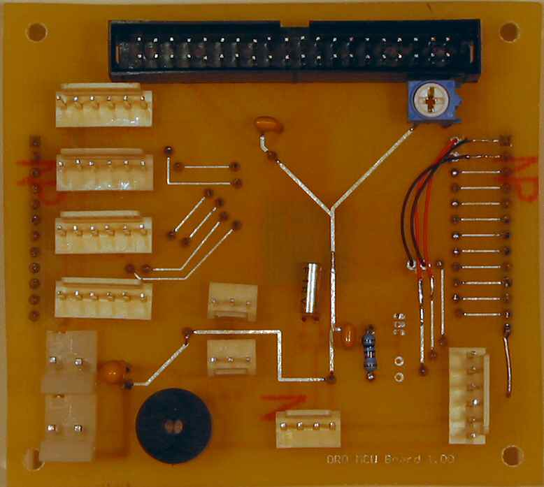 |
| Bottom | Top |
Notice the Atmega64 on the underside of the board. 64 pin surface mount chip. I was so wrapped that I actually soldered it to the PCB and it worked... eventually. You can also see the small jumper wires runing over the board. Two big mistakes. First I forgot to run ground to the keypad. Second, I missed the bit in the documentation that says MOSI and MISO pins (Master Out Slave In/Master In Slave Out) that are labelled on the chip do not actually do the MOSI/MISO ISP functions. You need to use the PDI/PDO lines. It took me a while to find that!
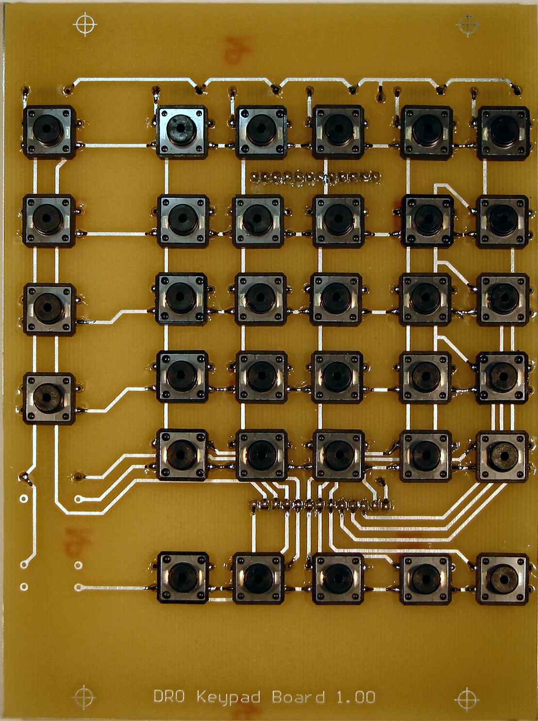
The keypad proved to be a bit of fun. I thought I'd simplify things and only produce a single sided board. It worked, kind of. The keys are all installed on the copper side of the board. Soldering was a bit tricky.
Which brings me up to date with the project. Most of the programming has been complete for the whole project. This was done using the RS232 interface to emulate the keypad and display. Next task is to program the keypad.
Then the display! To continue the over-engineered theme, I decided to use 5 rows of 10 display digits. Massive overkill. Each display is arranged in a 7x5 matrix. 5 rows by 10 columns means a matrix of 35 LED rows by 50 LED columns. This is why I decided the display would be a project in its own right. It will have an Atmega64, which will multiplex the display. It will use 35 I/O lines to light the rows, and 6 I/O lines to select the column.
Stay tuned for more.