Large Fixed Steady Rest
The fixed steady rest that came with my lathe can only hold a work piece with a maximum diameter of about 40mm. To turn the drum on my photoplotter, I needed to be able to hold at least 100mm.
Design
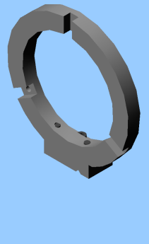
My design is based on that by Rudy Kouhoupt found in volume 1 of "The Shop Wisdom of Rudy Kouhoupt". It is a two piece design, comprising a large ring to hold the steady fingers, and a base to act as a stand and guide on the lathe ways. If I had a small foundry, I would have tried to cast the piece in aluminium, but the foundry is still on the to do list.
 |
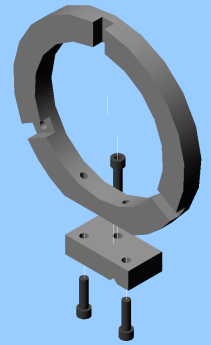 |
| The steady rest. | Exploded view. The steady is held together by bolts coming from underneath. |
The design is quite simple. The difficulty, however, is the fabrication. The ring was too big to fit on my lathe, so I planned to use my rotary table.
Machining
Base
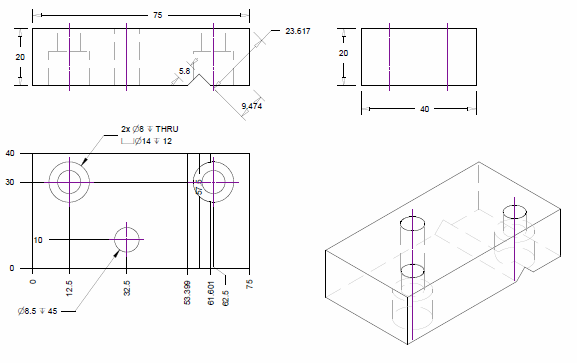
The base was made first. I this is just a block of mild steel, with a locating groove machined on the bottom to fit the lathe ways. The groove is 90° and was machined by placing the block in the vice at 45° and using a regular end mill.
There are two counter bored holes underneath to hold the ring. Another hole through the base clamps the steady to the lathe way.
Ring
The ring was made out of piece of cold rolled steel plate, 20mm thick, and approximately 200mm by 250mm. It looked like it had been used as a ramp to get an earth mover on and off its trailer - not a very nice finish.
Because the plate was large compared to the rotary table, the plan was to start by bolting the plate to the table with bolts positioned inside the ring. The outside of the ring is machined, then the slots for the lathe fingers. Holes are drilled for the locking screws for the fingers, which allows the hold down bolts to be moved to the hold the piece via the ring itself. With the hold down bolts out of the way, the inner circle of the ring can be machined. The sequence is described below.
The first step was to mount the plate on the mill against an angle plate ready to machine the surface where the ring contacts the base. This is machined flat, taking off only what is necessary to get a smooth surface, then drilled and tapped. I used M8 cap screws to hold the ring to the base.
Next, the base is attached to the ring plate. This is done so it can then be mounted on the lathe, with a dead center in the head stock to mark the center of the ring. This doesn't need to be terribly accurate as the steady fingers will correct any inaccuracies.
With the center found and the base datum known, the steady is disassembled and the plate is mounted flat on the mill. The bolts for the initial mounting of the plate on the rotary table are drilled. It is important that the bolt holes are position over the rotary table tee slots. My rotary table has 3 slots, and the smallest bolt circle going through bolts mounted on the table was about 109mm. It uses 3/8" tee slot bolts, so the bolt holes had to be this size.
The plate is then moved to the rotary table, centered about the center point, and the base mating surface used to find 0°.
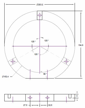
With the hold bolts on the inside of the ring, the outside of the ring is machined, then the slots for the lathe fingers. Holes are drilled for the locking screws for the fingers, which allows the hold down bolts to be moved to the hold the piece via the ring. Unfortunately the locking screws are 8mm in diameter so I had to make some tee nuts that with an 8mm thread. The drawing below shows the first phase of machining.
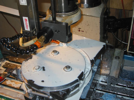
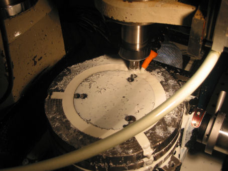
The photo below shows the machining of the outside of the ring. More of a profiling operation, cutting out the circle from the large rectangle. Note that the 3 holding bolts are in the center. All machining was done with a 16mm roughing cutter, and finished with a 16mm end mill.
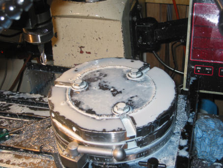
The picture below shows all machining on the outside is complete. The outside rim has been machined, the slots have been cut, and the front face of the ring has been surfaced. The holes for the finger locking screws can be drilled, then the hold down bolts moved into the finger slots.
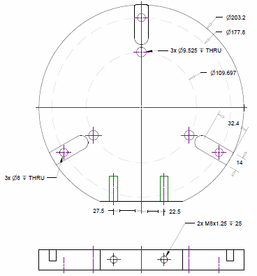
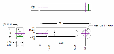
With the hold down bolts moved to the finger slots, the inner circle of the ring can be machined. A drawing of the complete ring is shown below. Only measurements for the final phase of machining are shown. Note the odd outer dimensions; they are to get the largest ring, based on the plate of steel I was machining.
The photo below shows cutting of the inside of the ring. The hold down bolts have been moved into the finger slots, hidden by the cutting fluid. Note the two sets of holes for the inside hold down bolts - measure twice, cut once!
Fingers
I made a new set of bearing fingers for the large steady. Because I was planning to machine aluminium, the standard brass fingers would do to much damage rubbing directly against the metal. I reused the holding nuts and bolts from the original steady to hold the fingers on the new steady.
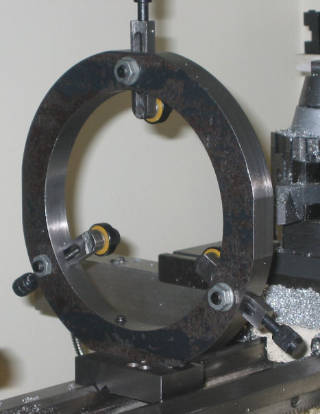
An M8 tapped hole is used to hold the bearings. These were skate bearings with an 8mm ID. An 8mm cap screw held it properly. The bearing fingers can be seen in the completed photo below.
Complete
The photo below shows the completed steady. This is its bad side; the cold rolled texture is still present on this face. Notice the two grooves and two clamping holes in the base - measure twice, cut once.