Lathe DRO and Speed Controller
Here are some details on the installation of linear scales on my 9x20 lathe, and the DIY DRO and speed controller I built for it.
Linear Encoder Scales
I originally purchased a pair of Chinese style scales to use on my lathe. However after installing I had problems with noise and jitter. I tried insulating them, and making modifications to the filtering code in the DRO, but never achieved a result I was comfortable with. In the end I gave up and switched to incremental glass scales.
I purchased the longer 500mm scale from Hare and Forbes, and the shorter 150mm scale on ebay, from the same seller I purchased the scales for my mill drill. (I just looked and can't find him). At the time, Hare and Forbes didn't have anything smaller than 200mm.
The design for the installation came from a couple of web sources, and an article in Model Engineers Workshop. It has been a while since I did, and I can't remember the variations.
X Scale
The drawing below shows the installation of the X scale (showing the back of the lathe).
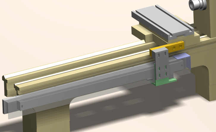
A 50x10mm aluminium bar is bolted to the lathe with a couple of cap screws. This bar provides the mounting surface for the lathe. Above and below each mounting bolt is a set screw used to adjust the positioning of the bar. When this bar is parallel to the X travel and vertically level, the scale is mounted to it. The scale has adjustment room for horizontal mounting. Once mounted, a DTI can be used to ensure it is parallel to the ways.
The scale carriage is connected to the lathe carriage through a series of brackets. In the picture, the scale carriage is bolted to the green lower bracket. The green lower bracket is connected to the grey upper bracket. The grey upper bracket is connected to the orange offset spacer, through a grey spacer. The orange offset spacer is bolted to the lathe carriage.
The complex mounting is for a couple of reasons. Firstly, most of the brackets have slotted mounting holes to allow for adjustment. Secondly, the connection between the lathe carriage and scale carriage needs to connect around the swarf guard (the translucent grey part). The connection also had to be offset to allow room for the Z axis. The small purple piece covers the end of the swarf guard.
Z Axis
The Z axis was a bit tricky. Most installations I have googled place the Z scale on the carriage next to the table on the tailstock side. I didn't want to do this for 2 reasons: first, it would cover up the gib strip adjustment screws, and second, it would force the tailstock further back from where it is now which I already have problems with. So I went with the "sticking out the back" design. The picture below shows the view from the back of the lathe.
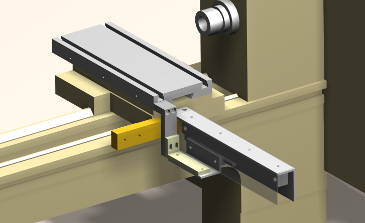
The same orange offset spacer, used to hold the X axis scale carriage, is used to mount the arm that holds the Z scale. The mounting arm is a piece of 3mm aluminium angle, with two mounting holes on the top, and two on the side. This allows it to be adjusted parallel with the movement of the cross slide table.
To connect the Z axis carriage to the cross slide table, another series of brackets are used. These brackets pass over the orange offset spacer to the scale carriage. This is necessary because the scale is on the tailstock side of the cross slide table. It can't be on the headstock side because there is no room (it would hit the motor).
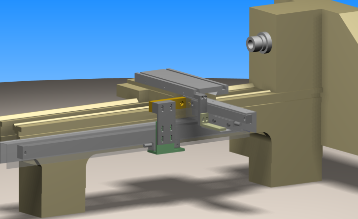
And here is the drawing of the X and Z axis. If you click on the drawing, you will get a dodgey 3D PDF file (you'll need the latest adbobe reader). It will allow you to view the model in 3D, but because of a bug, in Alibre Design, the cross slide table and carriage move when you try to animate it.
The Alibre Design files can be found here (.rar file, 680k).
Implementation
Here are some photos of the installation. It was relatively smooth sailing, although a couple of brackets had to be trimmed to fit.
The picture below shows the X axis scale, with the carriage at the end of the lathe. The glass scale is behind the aluminum swarf guard.
Here is another shot of the X axis looking down the tailstock end of the lathe. You can see the end of the scale and the carriage. The blurry thing to the right of the scale is the aluminium mounting bar.
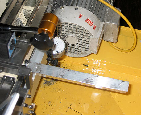
The picture below shows the set up for aligning the Z axis. The indicator will run along the Z mounting arm when the cross slide is moved. This setup, with the DTI at the side, does the horizontal alignment. The vertical alignment, which isn't as sensitive, is done with the DTI on top of the mounting arm. When the scale is installed, it will be horizontally align, but still needs to be tweaked to correct the vertical alignment.
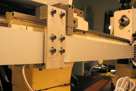
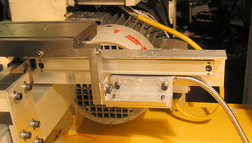
The photo below shows the Z assembly with the Z swarf cover.
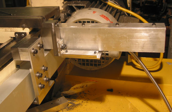
And, the final installation.
Digital Read Out
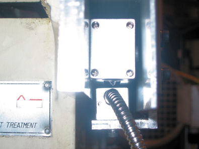
A while back I upgraded the motor of my lathe to a 3 phase, 1hp motor, controlled by a VFD, which takes 1 phase 240 volts and converts it to 3 phase 220volts. The VFD, or inverter, adjusts the frequency, which is the way it controls the speed of the motor. You can see the motor in the picture above.
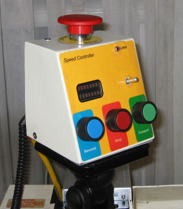
Below is a picture of the old speed controller. Emergency stop on top. Forward, Reverse, and Stop buttons on the front. Two 8 digit 5x5 LED displays. And a rotary encoder with built in push button (the silver stick), used to select menu options and tweak speeds and such. It also has a limit switch input which will stop the motor. I used this to automatically stop the motor when threading. Motor was control via the ModIO interface using a serial connection.
That was the old busted one. Here's the new hotness...
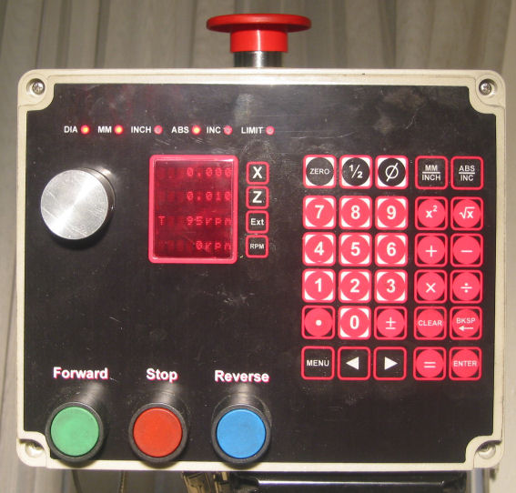
The DRO is mounted in a 250x200x95mm ABS enclosure, so that will give an indication of the size. It has 4 lines of 8 characters as the display, 34 buttons, forward/reverse/stop push buttons and an optical encoder as input. There is an emergency stop switch on the top. The emergency stop cuts power to the DRO, and the VFD via a relay inside the enclosure.
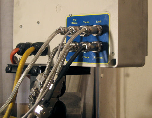
The DRO has inputs for X, and Z axis, a 3rd input (Ext) for an external device, eg digital calipers or micrometer. It controls the VFD via an RS-232 port talking ModIO. It has an input for the spindle tachometer, and an input for a limit switch. The rear connections of the DRO are shown below...
Scale Inputs
Because I originally installed Chinese scales on my lathe, the DRO hardware and firmware was created to read the Chinese scale protocol. When I switched over to glass scales, which have TTL quadrature input, I decided to leave the interface as Chinese and make converters. I could have just used the ShumaTec QCC-100, but they use PICs, and I thought I could squeeze it into a smaller package.
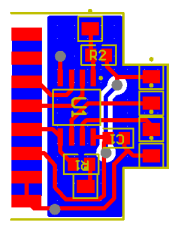
The converters can be seen in the photo above of the rear of the DRO. The short adaptor cable, converting the DB15 connector to a round 6 pin microphone connector. The circuitry fits inside the DB15 backshell.
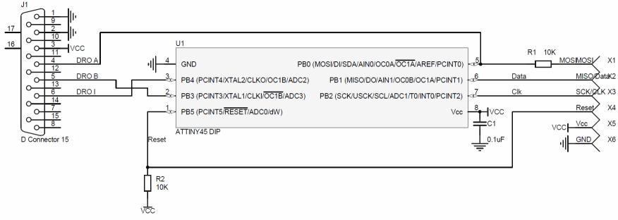
An attiny45 is the main bit of hardware. There's a decoupling capacitor, and a couple of resistors for Reset and the shared MOSI/DRO A line. The 6 pin microphone connector doubles as the programming interface (the connector on the right of the schematic).
The firmware is quite simple; read the quadrature signal changes then send the position signal every 20ms. The quadrature changes are read by the Pin Change interrupt. The data is sent via the main loop using two timers; timer1 overflows every 20ms signaling the time to send a new packet, and timer0 generates a 90kHz clock to send each bit when the Output Compare Flag is set. The built in 8MHz RC oscillator is used for the clock. The serial stream contains 2 data words (24 bits each): the absolute position and the relative position. In my implementation, the absolute position is relative to where the scale was when it was turned on. The relative position is zero until a pulse is received on the I (index) line of the scale. Then it is the offset from the index position to the start position. This allows the scales to be reposition after the power is turned off (although I never use this).
Here's the schematic.
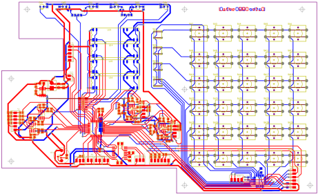
And the PCB.
The firmware can be found here
![]() .
.
DRO Main
The schematic and PCB for the original version of the DRO is shown below (click on the for the pdf version). This version is still wired for Chinese scale inputs. The current functional version has been heavily modified to support the glass scales. This includes removing the input filtering, and providing a 5v output rather than the 1.5v scales. Please, only use the schematics and PCB for ideas.
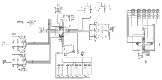
The most notable feature of the board is the dual microcontrollers. I put the keypad scanning functionality into a separate microcontroller and communicated back to the main controller via SPI. I could then use a smaller less expensive microcontroller as the main controller and also offload the keypad scanning processing.
The keypad processing is all done in the main loop. It scans each row and column for key presses. It uses a millisecond timer to debounce keys. When a key is sensed it is sent to the main controller via SPI. In this case, the keypad controller is the SPI master. There is an SPI data ready line (SPI_DRDY) which was designed so the keypad scanner would be a slave, but that wasn't used.
Keypad firmware is here
![]() .
.
The main microcontroller, an Atmega162, does all of its time critical work in the interrupts: PCINT (pin change interrupt) for the tacho, PCINT for user interface encoder, EXT0 for the X axis data clock, EXT1 for the Z axis data clock, EXT2 for the external device data clock, key presses via the SPI interrupt, and tasks scheduled via the timer0 millisecond interrupt. There are still problems with reading the Chinese scale protocol which leads to occasional glitches on the display.
The spindle tacho works by counting pulses and summing the time each pulse takes. Then to get the spindle speed, we divide the number of pulses we counted by the time over which this occurred, and scale accordingly. This helps get an accurate spindle reading at low speeds, compared with just counting pulses each second.
The main loop is responsible for non-critical tasks: updating the display, and implementing the user interface. It also executes tasks scheduled at a low frequency (less than 10 times per second), including the ModIO status updated, and PID loop updating.
The motor speed is controlled by a slow PID loop. Speed is controlled by setting the frequency of the VFD. There are some interesting side effects of the PID loop. The I term seems to take into account the different pulley ratios of the lathe, so there is no need set up and change pulley tables. There is an unfortunate glitch, which causes the motor to hit max speed unexpectedly; this might by an integer overflow in the PID loop, but I haven't debugged it yet. If the spindle stalls, like getting a parting tool stuck in the workpiece, the motor will continue accelerating to max speed until it is released; that needs to be fixed.
The main controller firmware is here
![]() .
.
Functionality
The keys and indicators on the DRO are shown below.
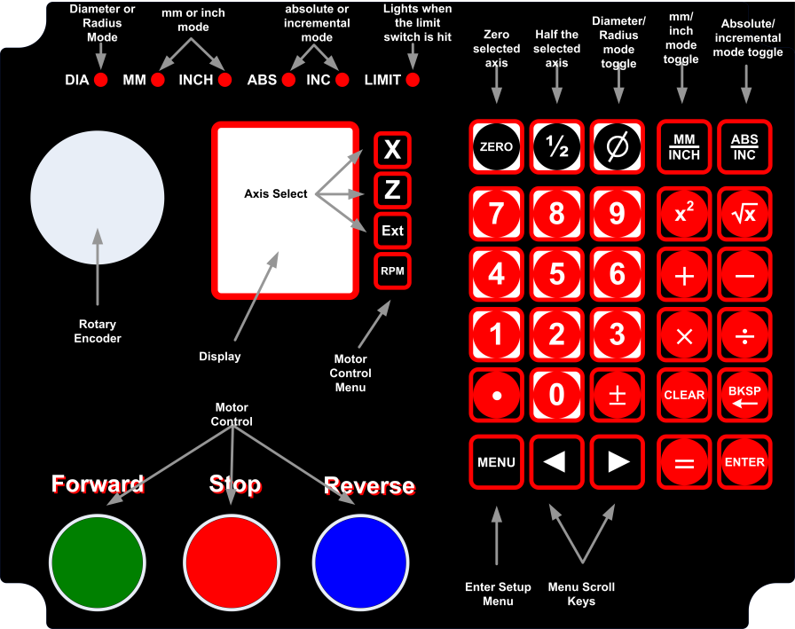
| DIA LED | Indicates diameter mode is on. The Z axis value shows the diameter, rather than the radius. In diameter mode, when the encoder moves one unit, the display changes by two units. |
| MM LED | Indicates the display is in millimeters. |
| INCH LED | Indicates the display is in inches. |
| ABS LED | Indicates absolute mode is on. |
| INC LED | Indicates incremental mode is on. I really don't know what abs/inc modes are supposed to do. All other DROs have them, so I do too. My implementation basically gives two work offsets that can be toggled between. |
| LIMIT LED | Lights up when the limit switch is closed. |
| X/Z/Ext button | Selects either the X, Z or external device axis for changing. When selected, a new number can be manually entered, or the zero button can be pressed to zero the axis, or 1/2 can be pressed to half the current value. On my mill, if the electronic edge finder is triggered, the axis is homed at that point (less the radius of the edge finder). I may do something similar to the lathe DRO. |
| RPM button | Enters the Motor Configuration menu. This menu gives options on how the RPM of the motor is determined. |
| Zero button | Zeros the current active axis. |
| ½ button | Halfs the value of the current active axis. |
| Ø button | Toggles between diameter and radius mode. |
| mm|inch button | Toggles between mm and inch mode. |
| abs|inc button | Toggles between abs and inc mode. |
| menu button | Enters the setup menu. |
| Enter button | Accepts the current value. If enter is pressed and nothing has changed, the menu is exited. The enter key is also used in the RPM menu. |
| Forward button | Starts the motor moving forward. If the motor was already running in reverse, it will stop the motor and move forward. |
| Stop button | Stops the motor. |
| Reverse button | Starts the motor moving in reverse. If the motor was already running forward, it will stop the motor and move in reverse. |
| Rotary encoder (Dial) |
The dial is used to set the motor RPM in some of the different run modes. It is also used to set number values in the menu, eg SFM. |
Setup Menu
The setup menu only has a couple of configuration items. Most of the configurable items are hard coded. Bad me.
| VFD Baud | Sets the baud rate to the VFD. One of 4800, 9600, 19200, 38400 |
| VFD Prot | Sets the VFD protocol. One of ASC 7n2, ASC 7e1, ASC 7o1, RTU
8n2, RTU 8e1, RTU 8o1. The VFD parameters are based on my VFD, a GS2 from
automationdirect.
|
RPM Menu
| RPM Mode | Defines how the speed of the motor is determined. The mode can be one of Material, Mat. DRO, SFM, SFM DRO, RPM, or Count. The different modes are described below. |
| SFM | Only available in SFM or SFM DRO mode. Specifies the current materials surface feet per minute value. This value is used to calculate the motor rpm. |
| Material | Only available in Material and Mat. DRO mode. Specifies the type of material being cut. It can be one of MldSteel, FreeCut, Aluminum, Brass, Bronze, CastIron, HardCast, Copper, Stainles, HighTens, SlvSteel, or Plastic. This value is used to calculate the motor rpm. |
| Cutter | Only available in Material and Mat. DRO mode. Specifies the type of material of the cutter. It can be one of ToolStee, HSS, or Carbide. This value is used to calculate the motor rpm. |
| Cut Type | Only available in Material and Mat. DRO mode. Specifies the type of cut. It can be one of Rough, Finish, Parting, Drilling, Reaming, or Threadng. This value is used to calculate the motor rpm. |
| Braking | Specifies how fast the motor will come to a stop when the Stop button is pressed, or the limit switch is set to stop the motor. It can be one of Fast, Medium, Slow. Fast is 0.3 seconds, Medium is 2.5 seconds and Slow is 4. Using Fast at high speeds with a large chuck is almost guaranteed to snap a v-belt. |
| Limit Sw | Specifies the function of the external limit switch. It can be Off, Light, or Stop. Off means nothing will happen. Light will light the limit LED and beep. Stop will stop the motor according to the Braking setting. The motor only stops when the limit switch goes from open to closed. I use this setting for threading. A better use of the DRO would be to specify the X coordinate to stop at. Something for the TODO list. |
| Zero Cnt | Resets the revolution counter to zero. See Count mode. |
RPM Modes
| Mode | Description | Dial Function | Display | |
| With an external measuring device | no external measuring device | |||
| Material | Material mode uses the Material, Cutter, and Cut Type settings from the RPM menu to calculate the required motor rpm. The diameter of the workpiece is set with the dial. | The dial sets the diameter of the workpiece. | Row 1: X Row 2: Z Row 3: External device Row 4: Cycles between entered diameter, target speed and actual speed | Row 1: X Row 2: Z Row 3: entered diameter Row 4: cycles between target speed and actual speed |
| Mat. DRO | Mat. DRO mode uses the Material, Cutter, and Cut Type settings from the RPM menu to calculate the required motor rpm. The diameter of the workpiece is determined by the Z axis value. As Z changes the diameter changes and the motor speed changes. This is effectively constant surface speed mode. | None | Row 1: X Row 2: Z Row 3: External device Row 4: Cycles between target speed and actual speed | Row 1: X Row 2: Z Row 3: target speed Row 4: actual speed |
| SFM | SFM mode uses the SFM value (surface feet per minute) from the RPM menu to calculate the required motor rpm. The diameter of the workpiece is set with the dial. | The dial sets the diameter of the workpiece. | Row 1: X Row 2: Z Row 3: External device Row 4: Cycles between entered diameter, target speed and actual speed | Row 1: X Row 2: Z Row 3: entered diameter Row 4: cycles between target speed and actual speed |
| SFM DRO | SFM mode uses the SFM value (surface feet per minute) from the RPM menu to calculate the required motor rpm. The diameter of the workpiece is determined by the Z axis value. As Z changes the diameter changes and the motor speed changes. This is effectively constant surface speed mode. | None | Row 1: X Row 2: Z Row 3: External device Row 4: Cycles between target speed and actual speed | Row 1: X Row 2: Z Row 3: target speed Row 4: actual speed |
| RPM | RPM mode sets the motor RPM directly from the value set with the dial. | The dial sets the RPM. | Row 1: X Row 2: Z Row 3: External device Row 4: Cycles between target speed and actual speed | Row 1: X Row 2: Z Row 3: target speed Row 4: actual speed |
| Count | Count mode is used to count the number of revolutions the spindle has made. Used for winding coils. The motor RPM directly from the value set with the dial. The Zero Cnt option in the RPM menu is used to reset the counter. | The dial sets the RPM. | Row 1: X Row 2: Z Row 3: External device Row 4: Cycles between target speed and actual speed (Hmm! Seems lacking) | Row 1: X Row 2: Z Row 3: cycles between target speed and revolution count. Row 4: actual speed |
TODO
- Fix the PID loop bugs. Maybe look at using the VFD's analog in rather than using ModIO.
- Redo the PCB. Get rid of the Chinese scale support and read the glass scales directly.
- Find and mount the DRO in a metal enclosure.