3d printed Hypocycloidic gearboxes I
I gave up trying to fix the Harmonic gearbox when I saw some examples of DIY hypocycloidic gearboxes.
I think I saw this on youtube first –
And then a bit of googling led me to a commercial producer, Darali Drives, and then to Zincland! http://www.zincland.com/hypocycloid/, where the author not only provides some nice technical links (you may need The Way Back Machine for some links), but also some software to generate the cam profiles.
This looked quite interesting from a few perspectives…
- High reduction ratio
- High efficiency
- Thin profile
- No sliding surfaces
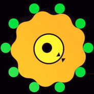
The last point is worth noting. The green circles in the picture above are called the roller pins. As the cam oscillates, its surface runs along the rollers. However, all of the DIY exampls on youtube and thingiverse (and the zincland example) have a single solid single piece outer that incorporates the pins, in effect making the cam slide against the pins. As plastic is very abrasive (that is, most 3d printed plastics), this is bad.
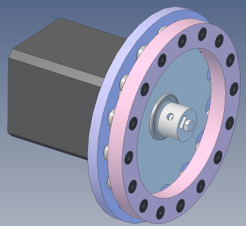
To me, the obvious solution was to use small bearings where the roller pins are. This led to version 1…
The small bearings used as the roller pins are SMR106 6x10x3mm. The bearings used for the eccentric are 6901, 12x24x6mm.
Sadly, this design didn’t really work. The mechanism turned fine, but the load on the 3d printed bearing centers kept shearing off.
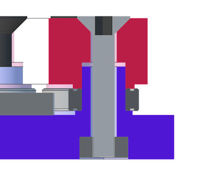
So, version 2…
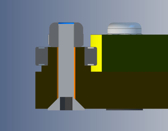
To strengthen the bearing mount, an M3 screw and nyloc nut was placed through the center. The cross section shows this better…
This kind of worked. The mechanism as a whole was much stronger, however, the 3d printed part was even thinner and was easily damaged during assembly and disassembly. Heavy loads still caused the bearing to push out and the cam to lift.
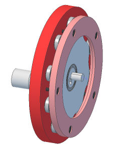
Version 3…
To stop the bearings moving they need to be held firmly on both sides. Version 3 uses a ring to help hold the bearings in position.
This time the countersunk screw comes in from the top into an embedded nut.
Better, but this became hard to assemble, and again fragile. The ring and base have to be aligned perfectly when assembling. Applying force will crush the 3d printed parts.
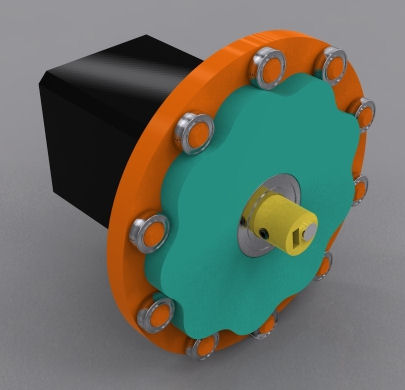
Version 4… Tubular!
Rather than flimsy 3d printed shafts to mount the bearings on, I decided to use small tubes. I used small sections of carbon fibre tube, as this was easy to sand down to get the bearings to fit snugly. The matte finish carbon fibre weave was the best; gloss finish appears to be another layer of epoxy that has to be sanded off to make the bearings fit. Pultruded tubes are easily crushed.
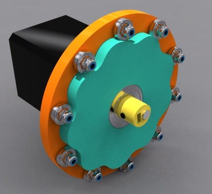
Click on the above image to view the 3d pdf. Note there are now less screws to hold the ring in place. These don’t go through the tubes as that was weaker.
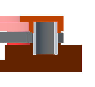
This has solved a lot of the problems. Applying too much force during assembly can still crush the 3d printed plastic. However, doing it this way means that there really isn’t any tricky shapes that couldn’t be machined on a cnc router.
Next, output…