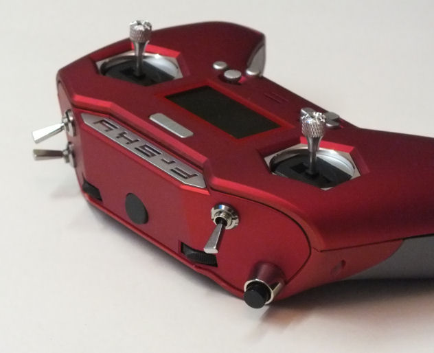
Taranis X-Lite Big Switch Upgrade
I got the Taranis X-Lite to use with DLGs (discuss launch gliders). It is small and light, and a lot cheaper than my DX8, which I was afraid of launching along with my DLG. However it doesn’t have a momentary push button (for launch) and the toggle switches are tiny – they are hard to find, and hard to toggle.
So, I upgraded them to grown-up switches.
The toggle switches I got from Banggood.com – they have a range of 2 and 3 position switches, with normal and long levers – I used normal length levers. The push button I got from my local electronics shop, SPDT Momentary Solder Tail Pushbutton and Dress Nut.
Disassembly of the X-Lite is described on a few websites/youtube videos – the trick is to use a credit card (or similar) to run around the seam to open it up.
Everything has to be removed to take off the top panel where the switches are, so be careful not to lose screws. The website I followed said the screws were all the same size, but they weren’t on my X-Lite. I also had 2 screws holding the case together, whereas his didn’t have any.
To ensure everything was going to fit, I 3D printed some “fake” switches. These were almost identical to the new switches, except the threaded shaft was a smaller diameter – the case needs to be drilled to fit the larger switches (from 4.8mm to 6mm).
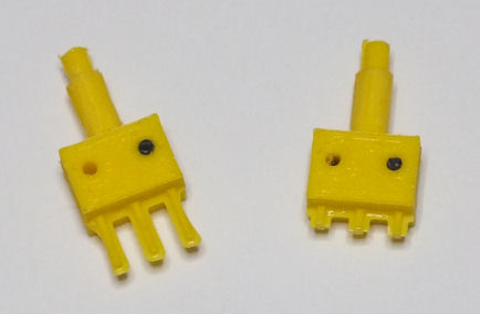
I found that the switches would fit, but the threaded shaft stuck out too far. I 3D printed some spacers pull the switches back into the case – this could also have been done with another nut on each switch. I also had to cut the solder tabs on the switches as they were too tall.
![]()
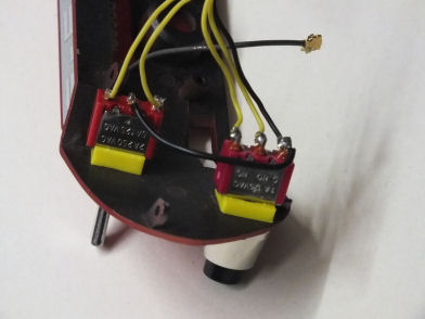
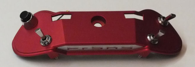
The images below show the switches installed. The mounting holes have been drilled larger.
![]()
![]()
The next issue is wiring. The existing switches are mounted on a PCB, with a small cable with connectors on each end attaching to the main board.
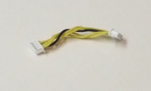
This is a standard 5 pin connector (but I forget the size). I found it faster just to use the existing cable. Because the cable is so short, I didn’t cut the ends. I removed the wires from the connector, and left the crimped contact on the end.
If you have already set up models on your X-Lite, you need to be careful which wires go to which switch. If you haven’t you can redefine them in using the X-Lite configuration. Note – you can also change the 2 position switches to 3 and vise-versa, then reconfigure the X-Lite to accept them.
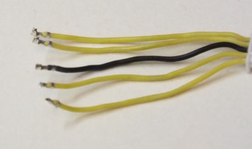
Next is the soldering. The black wire is the common ground, and the other wires are the signal pairs for each switch.
Double check which pin on the switch is common. The toggle switches I used had the centre pin as common.
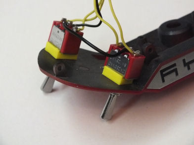
But the push button had common on the end.
Note the solder tabs have been cut right back.
And here’s the top panel ready to be reassembled.
The only issue I had with reassembly was accidentally disconnecting the tiny speaker. I had to open up the case again to reattach it.