Touch probe accuracy
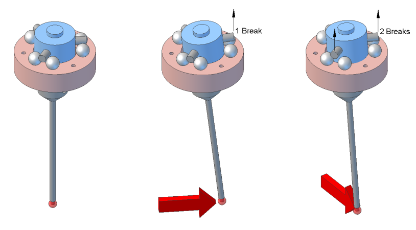
I purchased an inexpensive cnc touch probe many years ago and have always been concerned about the accuracy. These cheap probes (and some expensive ones) use a tripod type arrangement where 3 shafts, spaced 120 degrees apart, rest on pairs of balls. This makes a normally closed circuit, which is opened when probe shaft is moved. Given the geometry of the tripod, either one or two shafts will break the circuit depending on the direction of contact.
The probe is directly connected to the CNC controller board input, so the resistance of the touch probe circuit is important in the detection of the probe touch.
To try and measure this, I fixed a precision disc to the cnc router table, and wrote a gcode routine to probe the outside of the disc, moving from the outside of the disc, towards the center of the disc (the origin, x0 y0). The precision disc came from a 1″-2″ micrometer. This disc is used to “zero” the micrometer to 1″.
This is the gcode (units are in mm)…
#<radius> = 15
#<angle_step> = 5F15
G0 z25(PROBEOPEN probedisc.txt)
#<angle> = 0
o10 repeat [ 360/#<angle_step> ]#<x> = [#<radius> * cos[ #<angle> ]]
#<y> = [#<radius> * sin[ #<angle> ]]g0 x#<x> y#<y>
g0 z0
g38.2 x0 y0
g0 x#<x> y#<y>
(print,#<angle>, #<x>, #<y>)#<angle> = [#<angle> + #<angle_step>]
o10 endrepeat
Results
And here are the results…
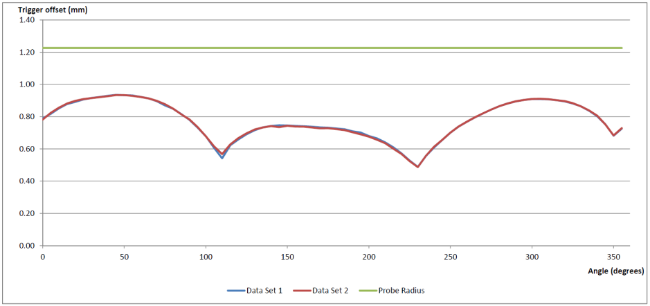
The chart shows the offset from the outside of the disc (1″). The probe tip diameter is 2.452mm. The green line shows the probe tip radius. This line is where an ideal probe would have triggered. The red and blue lines show the actual results from 2 test runs – very repeatable.
The chart shows 2 clear issues; one is the large offset before triggering – either an electrical switching issue, or the flexibility of the probe. The second issue is how the trigger point varies depending on the angle of approach of the probe. (there also may be an error due to the disc not being truly at the origin (and there may be backlash issues with my machine)).
Improvements
The first fix would be to add a sensitive detector to the circuit eg an opamp to detect a minute change in circuit resistance. Given that the results are also so predictable, the offset could be corrected based on the travel direction of the probe, but this would require the probe to be inserted into the spindle in the exact position every time.