Rotary Controller 2.0
This project has been a long time coming. Version 1.0 was a bit buggy, and the plastic container didn’t hold up well…
Version 2.0 has the following updates…
- Aluminium enclosure
- ST “blue pill” microcontroller
- OLED 20×4 character display
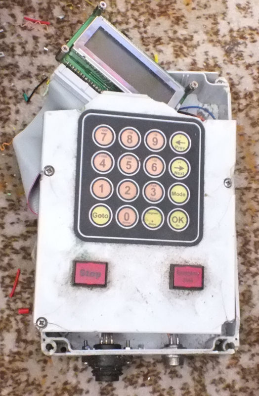
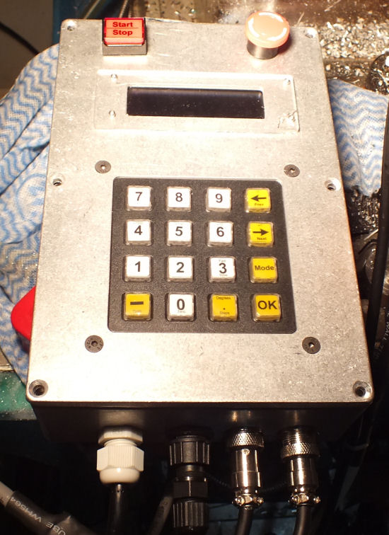
- Storm® illuminated keypad
- Stepper encoder input to monitor missed steps
- Spindle input for synchronous motion
- Support for 2 devices – rotary table and 4th axis
The insides are shown below…
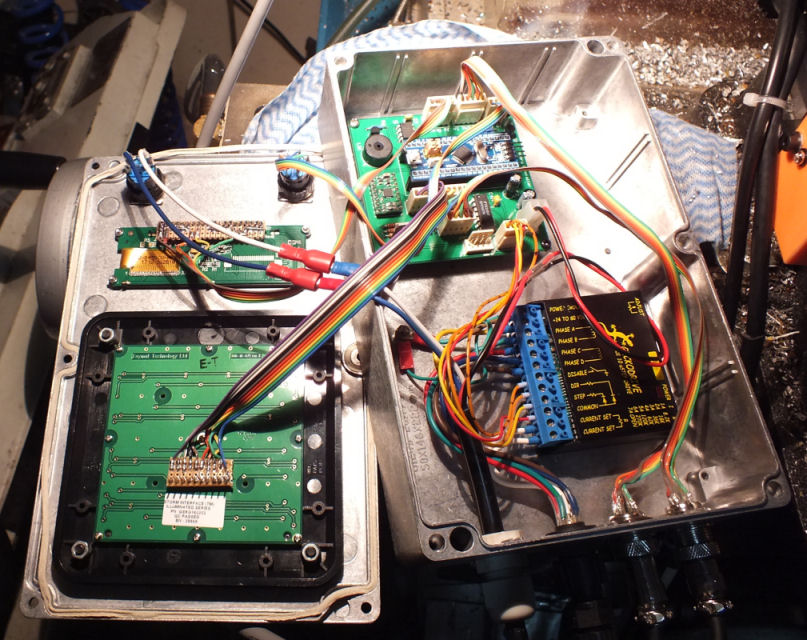
Note that the stepper driver, a Gecko G201, is now in the controller, not the power supply box. This means the stepper cable runs from the controller box to the stepper. This is more convenient as the controller is usually right next to the rotary table/axis.
Multiple Rotary Devices
In addition to my vertex 8″ rotary table, I also know have a cheap rotary axis (4th axis) with ER32 collet. I replaced the stepper with a stepper plus encoder, and 3d printed a cover over the belt drive…
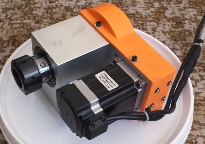
The stepper motor uses a 7 pin plug – 4 are used for the stepper coils, and 2 are used to set the Gecko Drive current limit, by using a resistor across the 2 pins. The 4th axis is a 3 amp stepper, while the rotary table is a 2 amp stepper.
Stepper Monitoring
The rotary controller supports encoder feedback from the stepper motor. This allows detection and recovery of missed steps – this was a common problem when using rotary table and forgetting to release the table locks.
The encoders are 3 channel differential – signals A, B and Z, being sent through a pair of wires. In the cable, on the controller end, the differential signal is converted to simple signal. Note – the Z signal is not used.
When a stepping error is detected, the illuminated keyboard glows red. You can then either recover, or reset home.
Synchronised Motion
The synchronised motion was added to support gear hobbing. A pattern was printed on inkjet photo paper and glued to the underside of the mill-drill spindle pulley…
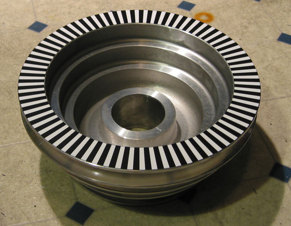
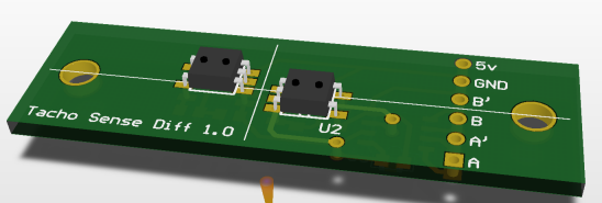
The sensor comprises 2 x Hamatsu P5587 photo reflectors, and a uA9638C differential line driver (on the bottom). Alignment and positioning is important. The sensors are positioned on the pcb to work with the printed encoder pattern dimensions.
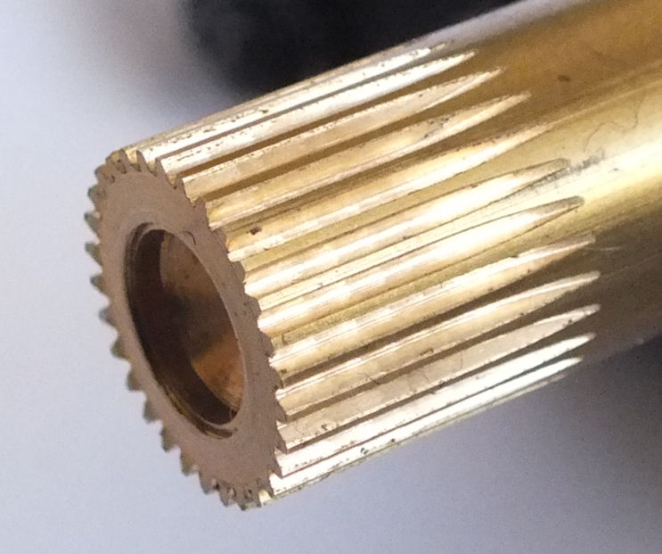
A quick test below shows a 30 tooth 0.3 module gear cut from some 3/8″ (9.525mm) brass stock, and a 0.3 module hob.
Source code and hardware files are available on https://github.com/ftkalcevic/RotaryController2.