Lathe Pendant
I've been tinkering for a while with USB, HID devices, and LCDs with the idea of building a snazzy pendant. This is the latest incarnation, the pendant for my CNC lathe, built with hidcomp and GenericHID.
Pendant Design
Here is a picture of the pendant. (click on it for a larger image).
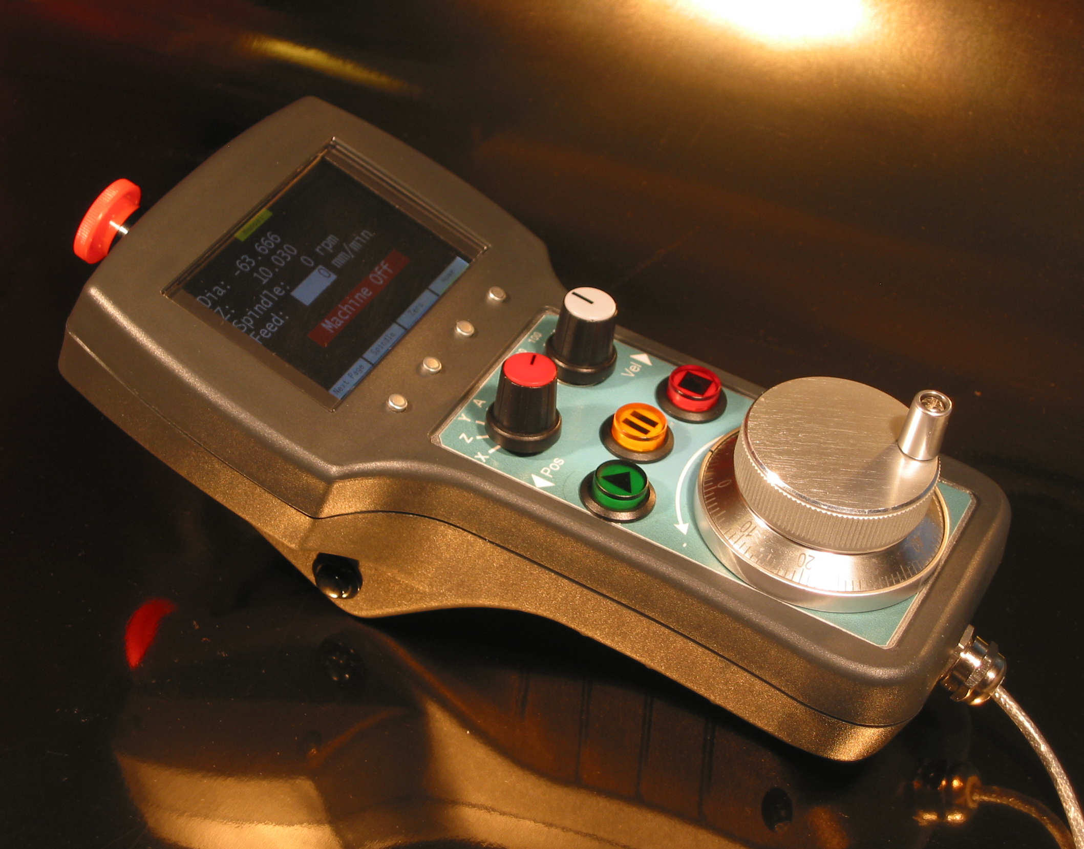
The pendant is based around a Rose-Bopla BG220 Handheld Enclosure. I got it from RS Components Australia, for about $AU75. For a hand held enclosure, it is quite large, but as anyone has who has built a pendant will tell you, you will quickly run out of space when adding buttons.
I didn't buy the enclosure immediately. I was tossing up between the Rose-Bopla enclosure, and the Box Enclosures 230-12-TW. I made CAD models of each and tried to fit the bits and pieces on each enclosure. I still wasn't sure whether I was going to use an encoder wheel or a joystick. The Rose-Bopla enclosure came with a cut out for the LCD and a lens and mounting hardware. The cut out and mounting space for the LCD is is an awkward size - it wont fit a stock 20x4 character display, but it is so big, a smaller 20x2 would look funny and waste lots of space. After a lot of searching on Google and ebay, I came up with two options; 1, get a smaller footprint 4x20 LCD, or 2, get a 3.2" TFT RGB LCD and build a controller board for it. From the photos, you can see I decided on the Rose-Bopla enclosure and the 3.2" TFT RGB LCD.
More details about the LCD and driver can be found here.
Using a large LCD and some small menu buttons will allow the pendant functionality to change. I therefore only need a small number of permanent buttons. I chose a Run, Pause and Stop button. It would have been nice to have a Spindle start/stop button too, but there was no room.
Functionality
The picture below shows the pendant layout. The LCD is a pretty good fit, with only a 5mm gap on each side. The cut out for the display is 78x49mm. All menu buttons and main buttons are illuminated with internal LEDs. These are wired up, but currently only the Pause and Stop button LEDs are used by the software.
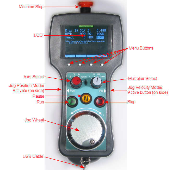
| Machine Stop | The machine stop button is a twist-to-release emergency stop button. I am only using it as a Machine Enable/Disable button. My lathe E-Stop cuts the power to the whole system. |
| LCD | The LCD display started as a 20x2 character display, grew to 20x4, and then exploded into a 320x240 16-bit colour display with two fonts displaying 45x22 characters or 22x11. |
| Menu Buttons | There are 4 buttons evenly spaced under the LCD. These are the soft-menu buttons. They invoke the action described on the menu row at the bottom of the LCD. They are illuminated buttons, but this feature is not currently used. |
| Axis Select | Used to select which axis to operate on. Select either one of the axis, X,Z,Y,A or Feedrate or Spindle Override. This will allow the jog-wheel to adjust the Axis position, or the feedrate override, or spindle override, and also used to select an axis to home. Note the bogus order of the axes. The pendant was designed for a lathe with X and Z axis, and I threw the Y and A on there, just in case. But thinking about it now, there is nothing lathe specific about the pendant, and it could be used for a mill too. The label on the pendant is a laminated inkjet printout, so it isn't difficult to print another, but the buttons and jog-wheel have through wires, so it is a serious disassembly to replace. |
| Multiplier Select | Specifies the step multiplier used with the jog-wheel when jogging an axis. x1 mean 0.001 mm per step, or 0.100 for a whole revolution of the jog wheel. x1000 is 1mm per step. Spindle and Feedrate override, will always adjust 1% per jog-wheel step regardless of the multiplier. |
| Jog Position Mode/Activate | The jog wheel will only execute if one of the activate buttons on the side of the pedant is pressed. The left button will jog using Position Mode (emc will move until the position is reached). This button is also needed as a general activate button, eg for feedrate and spindle override. |
| Jog Velocity Mode/Activate | The jog wheel will only execute if one of the activate buttons on the side of the pedant is pressed. The right button will jog using Velocity Mode (emc will move to toward the requested position only while the activate button is pressed). This button is also needed as a general activate button, eg for feedrate and spindle override. |
| Run | The run button. Pressing this starts the currently loaded gcode program running. If the program is paused, pressing the run button will run to the next line. |
| Pause | The pause button. Pauses the running GCode. Pressing the button again, resumes the gcode. This button will be illuminated when paused. |
| Stop | Send a stop command to EMC. This can be used to stop a program running, to stop a homing sequence, and other things. This button will be illuminated when a program is running. |
| Jog Wheel | The Jog wheel/dial. Use this in combination with the activate buttons to jog an axis or adjust an override. Also used to set the parameter values in a wizard. In this case, the activate buttons are not used. |
| USB Cable | The pendant is powered by and communicates across the USB bus, using a single wire. If a properly integrated E-Stop system was use, a separate high voltage wire (more than 5v) would be used for this. |
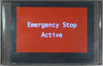
When EMC starts, the E-Stop warning screen is displayed. This screen is displayed whenever E-Stop is active. E-Stop must be cleared to use the pendant.
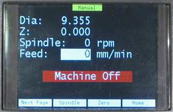
Manual mode screen. This screen can be used to jog, home and zero axes. The Next Page menu item is used to cycle though the pages. There's a menu item to do spindle things. The background colour of the Manual screen is black. Each different screen had a different background colour (Why? Because I can!) Which ever item is selected by the axis select switch is highlighted. In this case it is the feedrate override.
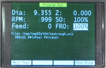
The Program Run screen shows the currently active program, optionally showing the current GCode line.
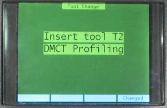
The manual tool change screen will prompt to have a particular tool installed. Pressing the "Changed" menu item will resume the program.
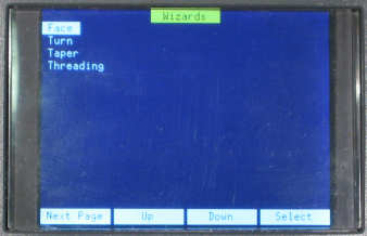
Select a wizard from the wizard screen. Scroll with the "Up" and "Down" menu items, and "Select" to enter the wizard.
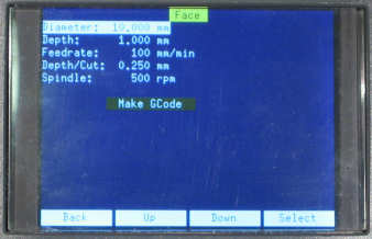
This is an example of the Facing wizard. Use the "Up" and "Down" menu items to scroll through the parameters. Pressing select goes into edit mode. In edit mode, turning the jog wheel will adjust the parameters. The "Make GCode" button, will generate the GCode for the wizard and load it into EMC, ready to be run.
Although the wizard can generate a whole GCode file in python, I am currently using EMC named subroutines that I have already defined for use in GWiz.
The implementation uses a combination of hal components, hal configuration files, and python script. A block diagram is shown below.
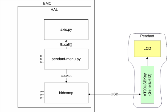
The pendant itself is built around a AT90USBKey, and the GenericHID software. This builds a USB HID device that can be used on any platform. The hidcomp userspace HAL component provides the interface to integrate the HID devices into EMC. All buttons, switches, LEDs, etc, are exposed as HAL pins.
hidcomp also provides a static interface to the LCD. Internally it has a set of statically defined pages that can be used to display EMC parameters (axis position, spindle speed, etc). There is also an external Socket based interface that allows direct drawing on the screen. The pendant uses a custom python script (pendant-menu.py) to display the menus and interact with the user. It also uses the tk module, and tk.call() to interact with Axis (in particular to load a gcode file, so Axis can update it's own displays). The python menu code uses the hal module to expose some pins to interact with other HAL pins (wired in a .hal file). It also uses the emc module to directly interface with EMC.
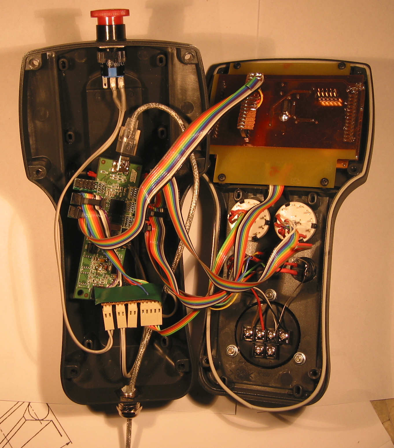
The picture above shows the insides of the pendant (click on it for a large image). It is using an AT90USBKey with extra components removed, 5v changes and with the wizbang wings. It is a tight fit. There aren't any suitable mounting holes on the AT90USBKey to mount it, so it just floats.
Here is a copy of my configuration as of 20th October 2009. I'll guarantee it will be different on the 21th. I like to fiddle!
Todo
This is the todo list...
- Test it. Yep, I haven't really used it. Once this is posted, I'll start using it with my CNC lathe and see how well it works, and start tweaking it.
- Menu enhancements...
- Manual spindle control
- More Wizards (only face and turn are implemented)
- Boring
- Threading
- Speed control by selecting tool type and material, then use CSS (constant surface speed) mode
- Tool offset configuration page
- GCode file browser/chooser