Graphic LCD
LCD
I was hunting for an LCD display for my lathe pendant and I found an ebay dealer that sold lots of different LCD displays. He had 2.5" and 3.5" displays. I wanted a 3.2" display. He said he could supply one and wanted to do the deal off ebay. I immediately knew I was going to get screwed, but I proceeded; it was only $US36.
To my shock and horror, the display arrived. All nicely packed. With touch screen too. The ebayer previously sent me a datasheet for the display and I knew it used an SSD1289 display driver. The chip has in built memory, so the driver I build will only need to push out data.
The plan for the LCD was to use the 320x240 resolution to make a high resolution display character based. With an 8x5 font, I could get 53x26 character display. My driver board will present the same interface to a stock character lcd module. The LCD driver chip supports an 8-bit interface. I had an atmega128l lying around, which would have plenty of flash memory for code and font data.
Version 1.0 8-Bit 8MHz
Bang! Bang! Bang! That's the sound of 3 bad design decisions.
1) Implement the character LCD module interface. On a slow microcontroller? I don't think so. The interface specification on most LCD displays show very tight timing between placing data on the bus and strobing the Enable pin. There is no way the microcontroller will be able to react to that.
2) The LCD driver chip has an eight bit interface. I don't know why I thought this was good? I have so many spare pins on the atmega128 that I should have used 16. Now, to send a pixel (16bits), I write 8 bits, strobe the enable, write the next 8 bits, then strobe enable. It should have been write 8 bits on port1, write 8 bits on port2, and strobe enable. In a loop with a counter, I could have improved performance by 30% or so.
3) The atmega128l, can only be clocked to 8MHz. Even when tweaking the output, the display updates were sluggish. Most modern atmegas will clock up to 20MHz. I could have had 2.5 times the performance with the correct chip selection. If I was adventurous, I could have tried the new atxmega, which can go up to 32MHz.
So, to solve problem 1), I decided to use SPI. This was built into both the at90usb1287 (my GenericHID project) and atmeag128l. It was handled internally to the microcontroller and interrupts controlled the flow of data. This luckily worked out well because my PCB accidentally exposed to the required SPI lines.
Unfortunately there is no solution to 2). The implementation was a two board design. One board held the LCD and LED power converter. The other board contained the microcontroller and power supply. The LCD I got had a solder type FPC (flexible printed circuit?). I build the board according to the data sheet, and soldered the LCD to it. The backlight worked, but that was about all. It turns out the datasheet was wrong and incorrectly described which pins to use in 8 bit mode. I had to make a new board, unsolder the LCD and solder it back to the LCD. The new layout worked, but the FPC was looking ratty and I wasn't about to risk unsoldering it again to upgrade to 16 bits. Oh well, next time.
And as for 3) read about Version 2.0 below.
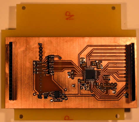
As mentioned above, this is a two board design. Two shots are shown below. The two halves are held together using single row header pins and sockets on each side of the board. Only one header is used to transfer data. The other header just holds the boards apart.
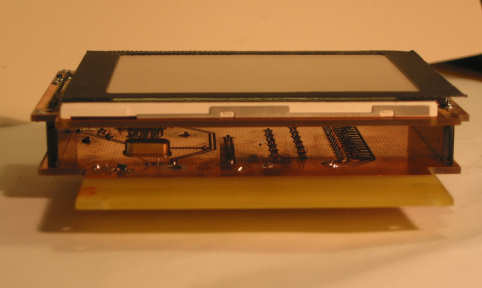
The MCU board is an irregular shape. This is to provide mounting holes so it can be fitted in its enclosure. The atmega128l is mounted on the back of the back pcb. This lined the pins up nicely for both the LCD (pins on the right), and the interface, header pins on the left, but not so far left. The mess of surface mount circuitry near the input header is the FET level converters. The inputs are 5v from the USB board, and the microcontroller requires 3.3v. The microcontroller uses 3.3v because the LCD also requires 3.3v.
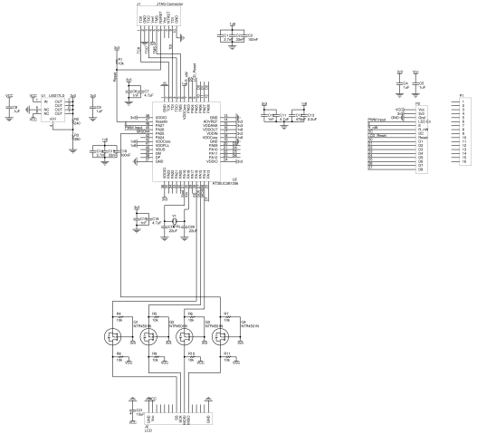
Here are the schematics and the source code.
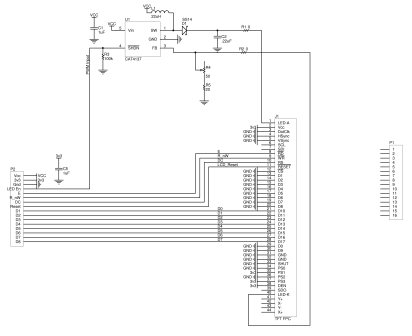
![]()
This was quite a painless project; everything work quite well, and the firmware was fun to write because of the performance tweaking. It is all written in C. Optimisation was done by looking assembly language generated by the C compiler, then optimising the C code until the compiler did the right thing.
Even after optimising, the display was still sluggish. Bring on version 2.0.
Version 2.0 32-Bit 60MHz
I wasn't happy with the 8-Bit atmega128l performance. Drawing rectangles and clearing the screen seemed fast enough, but draw text was sluggish. This version would serve as a fallback if my next adventure failed.I originally looked at the atxmega chip for version 2, but then the AVR32 chips caught my eye. My first experience with the AV32s was with their NGW100 demo board, based on the AP7000 chip. This required separate flash memory chips and RAM. The UC3B range, however, is more like the self contained AVR range with inbuilt RAM and flash memory. There are a couple of negatives though. Firstly it comes in a TQFP package. It's pins are 0.5mm apart. The other concern was the number of decoupling capacitors required. My board had 14 decoupling capacitors around the tiny board.
I bit the bullet and chose the AT32UC3B1256, a 48pin, 256KB flash, 32KB ram, 32-bit microcontroller which can run at 60MHz.
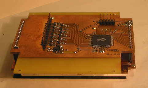
Because of the two board design, I only had to replace the microcontroller board. Top and bottom shots are shown below. The components on these boards are basically reversed (top and bottom). Because of the order of the pins on the microcontroller, everything fit better this way. These decisions are based on what limited boards I can build at home.
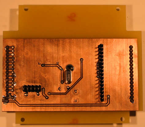
Because I was now only using SPI, the clutter around the input header was reduced. There really isn't much to the board. Inputs to the microcontroller. Outputs to the LCD. An LM317 to produce the 3.3v. And a crystal. That bloody crystal.
Atmel provide AVR32 Studio, the 32 bit version of AVR Studio. This, along with avr32 gnu tool chain, provides an eclipse based C/C++ development environment. There is also a software framework which provides "drivers" for each of the facilities.
Development was quite painless. I took examples from the framework to set up the clocks. I used the GPIO framework to do an LED flasher test program. From there, it was just a case of porting across the 8-bit code. Finally, move from debug to release, turn on the optimisation, -O1, and BOOM! Nothing worked.
After two days of positive moving forward, everything went haywire! The code would run, then it wouldn't run. Display data was coming out completely wrong.
It took another couple of days to work it all out. The first real problem was the crystal, shown in the picture above, or the right. It either had a lose connections, was shorting, or I fried it when trying to solder the case to ground. The symptoms were amazing. The display would start showing a test pattern, then just freeze. If I touched the board, it would resume. Bizarre.
I think I had other problems with setting the clock speed too. I didn't set the 1 wait state when running at 60MHz like I was supposed to. I was also trying to run at 66MHz for a while too - I saw that in pm_conf_clocks.c, so I thought I'd use it. Nah! I think that all contributed to the difficulties I was having.
The final problem I had was with the SPI data not synchronising with the NSS input. I haven't confirmed this, but I don't think the AVR32 does synchronise the SPI input with the NSS. I had to do this manually with the NNSS interrupt.
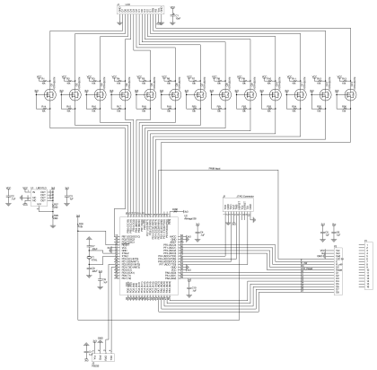
So, here's the schematic and the source.
![]()
I must say, I am impressed by the speed of the AVR32. The AVR32 can clear the LCD screen in about 0.01 seconds. Awesome! Some static action shots of the display can be seen on my Lathe Pendant page.