Limit Switches 2
The first version of my limit switches were causing problems because of the flimsy two pin connector. Movement, vibration, and just accidentally bumping the wires was causing them to fault. I thought about implementing the more complex design I mentioned after I had completed version 1. Instead I compromised and made a similar but more sturdy version.
Design
I did a lot of web searching for the ideal plug and receptacle to use on the limit switch. The perfect one was made by Tyco Electronics, part # 1445054-3. See the drawing of the receptacle below.
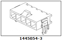
This has everything I need...
- A latching connection.
- Through hole mounting that can be soldered from the top.
- 3mm pitch is a bit bigger and sturdier than the 2.54mm pitch connectors.
- It has a low profile compared to the 3.96mm pitch connectors.
- And most importantly, the board anchoring posts are solderable metal legs on the side of the connector.
This would have made the most rugged connection to the limit switch PCB. Unfortunately, no distributor stocks them, and I would have had to order a packet of 266 at $1.00 each. There is a SMT version, but I didn't think that would be strong enough. There is also another through hole version, but it has a single clip type through hole post which would not be usable because the PCB has to mount flush to the limit switch.
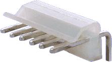
So, I settled with the standard 3 way 3.96mm 90 degree header. I used the ones from Altronics which are bent forward compared to the ones from Jaycar which are bent backwards. It looked like they would provide a better hold on the connector. The connector is shown below.
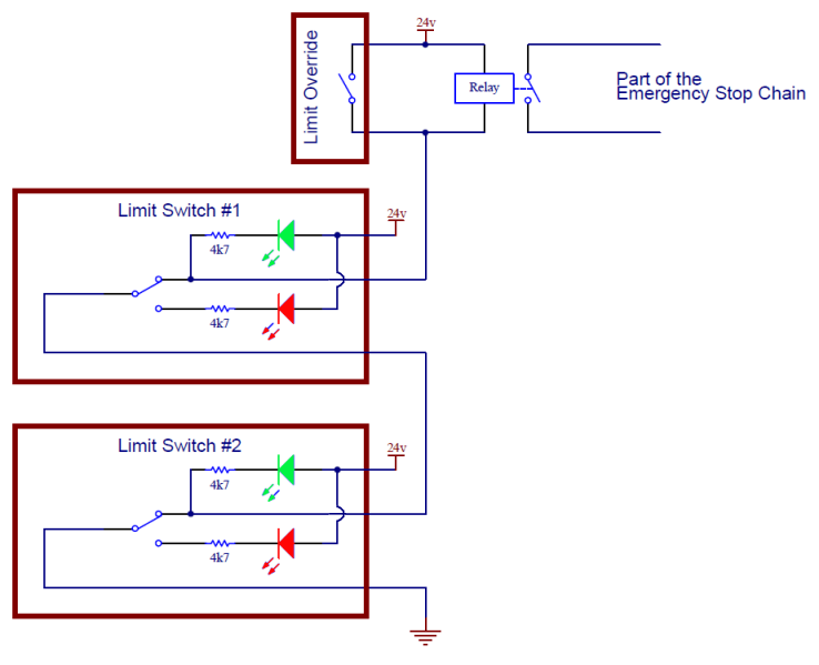
I also decided to jazz the switches up a bit by adding an additional green LED to indicate it was connected and powered up. This meant running 3 wires instead of 2. And also a change to the Limit Control Panel. The wiring diagram is shown below.
And in this version I actually insulated the exposed circuits. The limit switches used 24v which could have fried the PCB tracks if swarf caused a short.
Implementation
A completed switch is shown below.
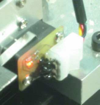
The PCB is covered in an epoxy casting compound, which you can't really see in the photo. It was a bit too runny to cover the legs of the connector, so they were painted with a few coats of liquid tape, the messy black stuff in the picture. The connections between the PCB and microswitch were also painted. I had plans to either create a cover, or make a mold and encase the part entirely in epoxy, but it was too difficult. The surface coating of epoxy and liquid tape is fine.
The connector is very tight fit. Because the plug uses large crimp pins, I had to use a heavy gauge wire. I used some 4 core security cable ~21 gauge wire.