PCB Agitator
I have tried two different types of etching for PCBs: the bubble tank and the shallow dish method.
I didn't like the bubble tank for a number of reasons. Firstly, they are large. Even the smallest tank sold in the PCB etching kits need 1.5 litres of etchant to cover the board. Secondly, I use Ammonium Persulphate as the etchant, which is only effective at temperatures above 60C. The aerating action of the bubble tank cools the temperature of the tank down and makes the etching ineffective.
The shallow dish method involves find a small shallow dish and filling it with just enough etchant to cover the board. I measure out about 250ml each time. This is enough to do about 2 boards of 150x100mm. To etch, the tray is placed in a tub of hot water and agitated back and forward, while I inhale the fumes from the tank. Eek! Hence the need for a mechanical solution.
Agitator Design
Movement
There weren't really many options here. I originally thought of using a simple cam system, like the picture below. This would fix the angle the tray was oscillated at, so I didn't use this method.
My plan though was to use an RC servo to agitate the plate. That way I could control the speed and the angle of oscillation just by programming the servo driving signal. Construction was also easier, using a simple wire link between the servo arm and the tray.

Heating
To keep the etchant at the correct temperature, the oscillating tray needed to be heated. I started by scrounging ebay for coffee pot or dinner plate warmers. I picked up a couple of cheap ones for about $20 and pulled them apart. These were simple resistance wire type elements, with very little insulation, both thermal and electrical, so for safety's sake, I decided to buy a safer heating element...
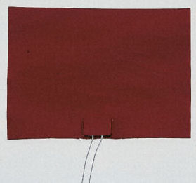
This is a silicon, flexible, self adhesive heater mat. It is 100x150mm, powered by 240v AC and draws 100W. I stuck it to the underside of the tray, which is 5mm aluminium plate. It works great, although I should have got the 200W model.
The particular model I purchased, (part #245-629, from RS Electronics) has a 20mm hole in the centre. I installed a LM335 temperature sensor in the hole to allow thermostatic control of the temperature.
Controller
The schematic for the controller is shown below. Click on it to see a pdf version.
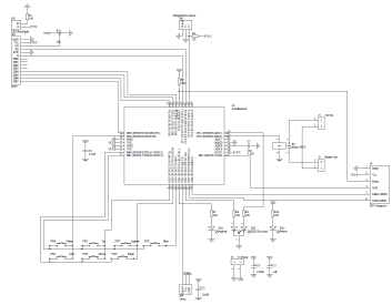
On the PCB are the buttons, LEDs and relay. Connectors are provided for the LCD, heater mat, servo, and temperature sensor.
The Assembled Unit
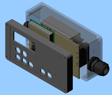
This was one of the first projects I completely did in CAD before any machining. Here's the completed CAD image...
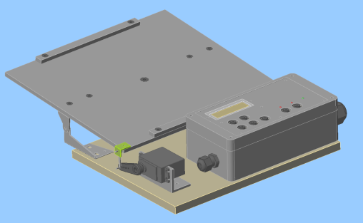
And some detail of the controller...
Here's the actual controller...
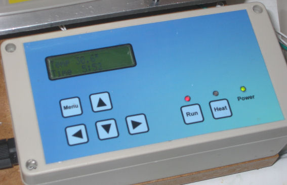
The panel is made using a vector drawing program, printed on an inkjet printer, then laminated. The holes for the LCD and LEDs are carefully cut out before laminating.
Software
The controller software has two modes: run mode and menu mode.
In run mode, the current temperature is displayed, and the elapse time since Run was pressed is displayed.
Pressing the menu button puts you in menu mode.
Menu mode allows the user to change configuration options. These are...
| Ag. Period | Specifies the period, in seconds, of the tray agitation. About 1.6 seconds works well. |
| Ag. Distance | This is the distance the tray will travel in an oscillation. The units are in ms, specifying the servo pulse width. It is not necessary to know this, as when the value is changed, it is updated immediately, so you can visually see the updates. |
| Ag. Home | Where the tray stops when it stop agitating. Again, this is in ms, specifying the servo pulse width, but it can be update dynamically. |
| Temp Cal. | This value is used to calibrate the temperature. To use it, use a thermometer to measure the actual temperature of the tray, and then set this value. The controller will map the current measured value to this one. The LM335 sensor is linear and cross zero, so only one sample is needed to calibrate it. |
| Temp Hi | Used to set the thermostat high level, ie the heater mat is on until this temperature is reached, then it is allowed to cool to the low level, then switched on again. This is to prevent fast switching of the heater. |
| Temp Lo | Used to set the thermostat low level. |
The Run and Heat buttons work in either mode. You can oscillate the table without heating it - useful for developing and tin plating.
The Run LED is lit when the tray is oscillating. The Heat LED is orange when turned on and heating, green when on and not heating (high level to low level period), and off when the heater is off.
Source is here.
In Use
Here's the obligatory action shot.
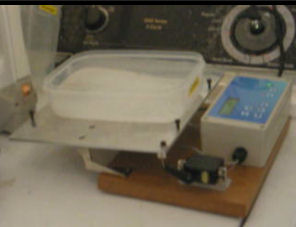
Or better yet, click on it for an action movie (1.2MB)! Apologies for the shaky camera work. Or did I do it deliberately for the sea sickness sensation?
The container is plastic and doesn't transfer the heat very well. I am currently using a metal tin, with an anti-scratch/stick coating. It was only $2, which is why it has started rusting. Next time I'll try an uncoated tin and paint the inside with automotive acrylics.
Next version
The agitator has a few short comings.
Firstly the heater element isn't powerful enough - 200 Watts next time.
Also, a buzzer and a timer would also be helpful.
The thermostat isn't very accurate. It is on the bottom of the plate at the sensor of the heat source and reads a temperature a lot higher than the top side of the plate. I'm not sure how to fix this. I could probably use one of the super thin PC CPU temperature sensors. I think they are simple NTC (negative temperature coefficient) resistors which change their resistance as the temperature changes (resistance decreases as the temperature goes up).