Mini Linux LCD Monitor
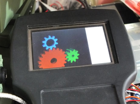 |
| LCD monitor mounted in a Rose-Bopla BG220 Handheld Enclosure |
The first iterations of the LCD display were "smart" displays - they had intelligence to draw text, lines, etc. This meant to use the display, applications had to be specifically written to produce output that could be rendered by the display.
This became annoying having to write a yet another GUI interface for LinuxCNC, so I started looking into making the LCD display act as a mini LCD monitor that X-Windows could use.
This turned out to be simpler than I expected. I had previously purchased a FingerVu 436; a 4.3" USB LCD monitor with 480x272 resolution. This didn't work properly on linux, so I needed to modify the driver to make it work correctly (see here). After seeing how simple the driver was, it was clear I could use this for my device driver.
The linux driver uses a virtual Frame Buffer - that is, the driver duplicates the memory of the display in computer memory (400x240x16bits) and sends block updates every now and then when the buffer changes. Because my LCD is small (400x240), the worst case update is 400x240x2 = 230400 bytes for a full screen update. At the 480Mbps theoretical maximum for USB High Speed, I should be able to achieve a worst case refresh rate of 200Hz, way more than I need.
So why not just use the FingerVu 436? Firstly it is bigger than what will fit in my pendant - 3.2" is the max. Secondly, it draws a lot of current - the FingerVu 436 comes with a special dual lead USB cable (it must connect to 2 USB ports) implying it uses up to 1 amp of current.
Speed Improvements
I was impressed with the speed of the AVR32 chips, so I looked through the Atmel catalog and found the AT32UC3A3 family. In particular the AT32UC3A3256S. These chips have 2 killer features: EBI and USB HS.
External Bus Interface (EBI)
The AT32UC3A3 series of microcontrollers have an external bus interface - they have built in hardware to communicate with external memories. Static memories have a simple interface - Address, Data, WR, RW - which coincidentally is the same interface as the graphic LCD. This means we can use the EBI interface to drive the LCD.
Why is this good? Performance and simplifying the code are the main reasons.
When the interface is set up correctly, it is possible to write to the LCD in a single instruction...
#define LCD_COMMAND_ADDRESS     (AVR32_EBI_CS0_ADDRESS + (1<<22))
#define LCD_DATA_ADDRESS        (AVR32_EBI_CS0_ADDRESS + (1<<21))

#define LCD_COMMAND             ((volatile uint16_t *)LCD_COMMAND_ADDRESS)
#define LCD_DATA                ((volatile uint16_t *)LCD_DATA_ADDRESS)

*LCD_COMMAND = cmd;
*LCD_DATA = data;
This example sets the command, then writes a data word. These are 16bit transfers. Using bit-banging methods, you need to...
- Ensure the direction of the data bits are set to output
- Write the data to the data bus.
- Set the data/command bit.
- Toggle the WR bit.
data = *LCD_DATA;whereas using bit-bang methods, we would need to change the direction of the data bus first.
The LCD is wired up to the microcontroller as follows...
| LCD | Microcontroller |
|---|---|
| ~CS | GND |
| ~RD | EBI_NRD |
| ~WR | EBI_NWE0 |
| RS | EBI_ADDR21 |
| DATA0-15 | EBI_D0-EBI_D15 |
Note that the LCD RS line, used for selecting between command and data, is wired to the EBI address line. This means the data and command registers are effectively memory mapped to two different addresses in the microcontroller's address space.
The configuration of the EBI isn't quite as simple as just wiring up the correct pins. The timing of when data is placed on the bus, when the WR/RD pins are strobed, and when new data can be placed on the bus, must be set correctly. My initial attempt, based on the timing data in the LCD data sheet was too fast, so I had to slow it down a bit. Regardless, it was much faster than bit-banging.
High Speed USB
The High Speed USB is capable of transferring 480Mbps, whereas Full Speed USB peaks at 12Mbps. This makes a huge difference when transferring screens full of information at time.
At 480Mbps, or approximately 48M bytes/s, that is huge volume of data for a 60MHz microcontroller to handle. The USB peripheral normally operates by reading the USB data into a memory buffer, then alerting the microcontroller application that there is data present. The application can then process the data. Even with double buffering, this causes a stall in the USB data flow.
Luckily, the AT32UC3A3 microcontroller series USB peripherals support DMA (direct memory access) transfers. With a DMA transfer, you tell the microcontroller where you want to place the data. This can be any memory address you want. And given that we are using EBI to access the LCD, we can transfer the USB data directly to the LCD at the full transfer speed.
Protocol
At the moment, everything about the device and communications is hard coded. The linux driver expects the device to be a 400x240px LCD with 16bit pixels (R5G6B5) using a R61509V display driver.
There are 3 commands...
| CMD_BOOTLOADER | Execute the boot loader. Atmel DFU can then be used to update the firmware. |
| CMD_SET_BACKLIGHT | Set the device backlight intensity. |
| CMD_BITBLT |
Copy a block of data to the LCD. This command is split across 2 or more USB packets. The first packet contains the rectangle of the display data that is going to be copied... uint8_t cmd; uint16_t x; uint8_t y; uint16_t width; uint8_t height;This packet is received using the microcontroller's standard double buffered transfer method. After it has been processed, the LCD is set up to receive the data, and the USB DMA transfer is set to move the data directly from USB to LCD. There is a potential race condition here, but as yet it hasn't been a problem. |
Schematic
The schematic is shown below...
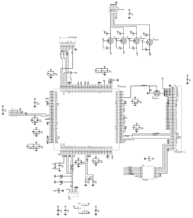
The schematic is pretty simple. The important parts are...
- Microcontroller connected to the LCD. Data/address/WR/RD lines connected.
- 5v to 3.3v low voltage regulator
- USB connection
- Many decoupling capacitors
- MOSFET for controlling the backlight intensity via PWM output
- SPI interface with voltage level conversion
- JTAG interface
- Serial Port
- Touch screen controller
Code
Below are links to the firmware and the linux device driver.
The firmware is really crappy alpha/prototype software. It originally started out as a smart LCD with USB Serial interface. All that code is still there, but just not called. There is also code there to implement a bit-banged interface. The core code to implement the BITBLT command is in udi_cdc.c:udi_cdc_data_recevied(). This is the interrupt callback when data has been received by the USB CDC (serial) interface - that is wrong in so many ways.
The firmware is here ![]() . It is built with Atmel Studio 6.
. It is built with Atmel Studio 6.
The device driver firmware is a hacked version of udlfb. It has only been run and tested on Ubuntu 10.04.01 LTS, kernel 2.6.32-122-rtai.
The driver is here ![]() . Run make, then make install, probably as root (using sudo).
I'm not an expert at linux device drivers, so if it doesn't build, google for help.
. Run make, then make install, probably as root (using sudo).
I'm not an expert at linux device drivers, so if it doesn't build, google for help.
Action Shot
Here's a youtube video showing a couple of apps running, including LinuxCNC. Unfortunately the LinuxCNC Axis application has a title bar, menu and tool bar, so after displaying that, there is not much room for anything else. The video shows an early version of the firmware not painting properly when dragging the window. (EBI running too fast)
Future Enhancements
- Query the device for its details. It should return the EDID of the device, which will report the resolution at runtime. It also needs to identify the LCD chipset, or the capabilities of the chipset in case there are more hardware features we can take advantage of. This will allow different size LCDs and different chipsets to be supported.
-
Touch screen support. The LCD already supports a resistive touchscreen, and there is an touch screen controller chip
on the PCB, but it is just not implemented yet. My first project will be a pendant for my mill, and the LCD will be mounted behind
glass so you won't be able to touch the LCD.
This will require a 2nd USB device, a HID device, to be implemented. - A bit more debugging. The device driver caused linux to crash/reboot on startup, but that seems to have gone away. This may be because the device reports itself as a CDC serial device - a remnant from the initial source starting out with a USB serial interface.
- Tidy the code. The firmware is a hack of multiple different versions of the LCD firmware. I also need to remove, or at least tidy, the ASF USB code. There is a lot of redundant code in there.
- Build a LinuxCNC gui for the display - something that can efficiently use the 400x240 display. I started writing a new QT GUI that defined the display with XML, but the performance was pretty poor, and the size of the task was growing. I'll need to look at the latest generation of LinuxCNC gui tools.