Photoplotter
When making PCBs, I've always found that creating the artwork was the trickiest part. I use a Xerox DocuPrint 240A, 1200dpi laser printer. It has problems...
- Large black areas come up grey and streaky
- The y dimension is incorrect - a 100mm line will print out at about 99mm, which doesn't seem bad, but when you have a 40pin DIP IC, or a dozen 2 way terminal blocks you want side by side, it can be a squeeze to get them to fit.
- Poor paper handling - as the paper is pulled through the machine, it tends to wiggle from side to side. Two lines running in the y direction on opposite edges of the page, will be different lengths. This result is inconsistent, which makes it difficult to align two sheets when doing double sided boards.
- Poor resolution - although the printer prints at 1200dpi, the toner splatter means the results are never near that. The results I get from printing at Officeworks, on transparency, using the table size "document centres" is amazing. High resolution and crisp sharp lines (looked at through a microscope at 100x). This isn't a problem for PCBs, but I'd like to try some photo etching small parts for Z-Scale model rail.
So, the next logical step (it's logical to me) is to build a photoplotter.
What's a photoplotter?
A photoplotter is a printing device that exposes light to a photo sensitive film to produce output. The film is then developed like traditional photos to get the result. There are 2 types of photoplotter, vector type and raster type. Vector plotters move the exposure light anywhere in 2D space to create the image. Need a line from point A to B? No problem, just move from A to B. These are similar to old style pen plotters. Raster plotters, are more like a dot matrix printer, sending out one line of dots, then moving to the next to create an image.
I am building a raster drum photoplotter.
A drum spins at high speed, and a laser moves along the length of the drum exposing the image. Each revolution of the drum allows the laser to draw one raster line. After the line is complete laser steps along the drum. Note that this is opposite to a dot matrix printer; the print head moves backward and forward to produce the line, while the drum rotates slowly to move to the next line.
Design Considerations
The initial design requirements are what I would like to be able to produce. They will all be changeable by modifying various components, like the drum speed controller, stepper controller, frequency multiplier, etc. (more on these later.)
Target requirements...
- 4000dpi output.
- A4 size output.
Design of the resolution comes down to the design of the drum size and position feedback for the x-axis, and stepper steps and screw pitch for the y-axis. and then the data through put issues.
Size
To fit A4 size paper, we need a drum length of at least 297mm long, and a circumference of 210mm. Allowing a couple of centimetres for taping the film to the drum, the diameter must therefore be a minimum of (210+20)/π = 73mm. My local aluminium supplier provides stock sizes of 75, 80 and 100mm. I chose 100mm, which will give me a maximum page width of 314mm. The page height was specified by the ballscrew length that I found on ebay. It was quite long giving me a maximum page height of 410mm.
Resolution
For the x-axis, we use an incremental encoder attached to the drum axle, a 2500 cpr US Digitial encoder, with Index pulse. Every time the drum rotates 1 revolution, the encoder pulses two position data channels 2500 times, channels A and B. These outputs are out of phase by 90 degrees. This can be used to quadruple the pulses, pulsing each time there is a change to A or B, which quadruples the pulses to 10,000. This is a bit tricky knowing how long to make a complete pulse cycle. To simplify the electronics, I only generate 5000 pulses, changing the output every time there is a state change - one state change gives a rising value, the next change drives a low. This gives a symmetrical pulse train, which will be handy for the frequency multiplier.
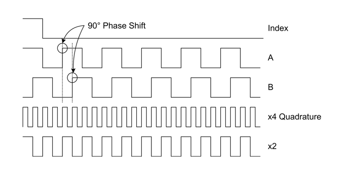
The Index pulse is used to indicate the start of a page. Each time the drum rotates, the encoder generates 1 index pulse at exactly the same place. This is used to indicate the start of the page.
After all that, the resolution for the x-axis is the circumference divided by the number of divisions. For the 100mm drum and 2500cpr encoder we get, 100π/(2 x 2500) = 0.063mm pixel pitch, or about 404 dpi. This doesn't get the required dpi, so a frequency multiplier is used.
Based on the CD4046 Phased-Lock loop chip, the frequency multiplier takes the input pulses and generates an output stream at a multiplied factor that we need. In this case, x10. This will give a resolution of 4040dpi. This value can be tweaked in the printer driver.
The y-axis, or that stepper axis, requires each step of the stepper motor to move 1/4000" to give 4000dpi. This is driven by the ability of the motor to microstep, and the pitch of the ballscrew the drives the laser carriage. My photoplotter uses a vexta 5 phase stepper motor, with mciro steps programmable from 500 to 125,000 steps per revolution. Although 125,000 is a ridiculously fine step, it can be used to define step multiples and hence get a better approximation to our target dpi. For example, if we need 600 steps per revolution, we can use 125,000, but step 208 times per division. Unlikely, but useful.
The stepper motor drives the ballscrew, an NSK WFA1405. The important number here is the 05, which means the carriage moves 5mm each revolution of the screw. So, to get 4000dpi, or 157dpmm, we need a step resolution of 157dpmm * 5mm = 787.4 steps per revolution. Looking at the stepper motors microstep range...
| Mode | steps/rev | Step Count | Actual dpi | Error % |
| 0 | 500 | 1 | 2540.00 | 36.50 |
| 1 | 1000 | 1 | 5080.00 | -27.00 |
| 2 | 1250 | 2 | 3175.00 | 20.63 |
| 3 | 2000 | 3 | 3386.67 | 15.33 |
| 4 | 2500 | 3 | 4233.33 | -5.83 |
| 5 | 4000 | 5 | 4064.00 | -1.60 |
| 6 | 5000 | 6 | 4233.33 | -5.83 |
| 7 | 10000 | 13 | 3907.69 | 2.31 |
| 8 | 12500 | 16 | 3968.75 | 0.78 |
| 9 | 20000 | 25 | 4064.00 | -1.60 |
| 10 | 25000 | 32 | 3968.75 | 0.78 |
| 11 | 40000 | 51 | 3984.31 | 0.39 |
| 12 | 50000 | 64 | 3968.75 | 0.78 |
| 13 | 62500 | 79 | 4018.99 | -0.47 |
| 14 | 100000 | 127 | 4000.00 | 0.00 |
| 15 | 125000 | 159 | 3993.71 | 0.16 |
Based on the available step modes, Mode 5, 4000 steps/rev, stepping 5 times for each line, will give 4064 dpi. This looks to be the best option, however, waiting for 5 micro steps to finish may cause issues, so Mode 1, may be an alternative, although bumping up the resolution to 5080 dpi.
Throughput
The throughput determines how long it will take to generate a page. Given our selected resolutions, we can estimate the speed of generation, and the rate at which we need to supply data...
| Drum Speed (Hz) |
Speed (RPM) |
Motor Speed (RPM) |
Encoder Rate (Hz) |
Time sec |
Data Freq (Hz) |
|---|---|---|---|---|---|
| 1 | 60 | 600 | 2,500 | 66.6min/in | 50kHz |
| 10 | 600 | 6,000 | 25,000 | 6.6min/in | 500kHz |
The motor speed is based on a 1:10 pulley ratio. This will most likely be 1:5.
Spinning the drum at 1 revolution per second, 60 rpm, gives a comfortable 50kHz data transfer rate, but at 66 minutes per inch, it will take 4½ hours to print a 100mm PCB board. At 600 rpm, it will take about 26 minutes, however, the data will need to be supplied at 500kHz, and the laser and optics must be able to handle that. This will all be finalised through trial and error.
Mechanical and Electrical Design
Overview
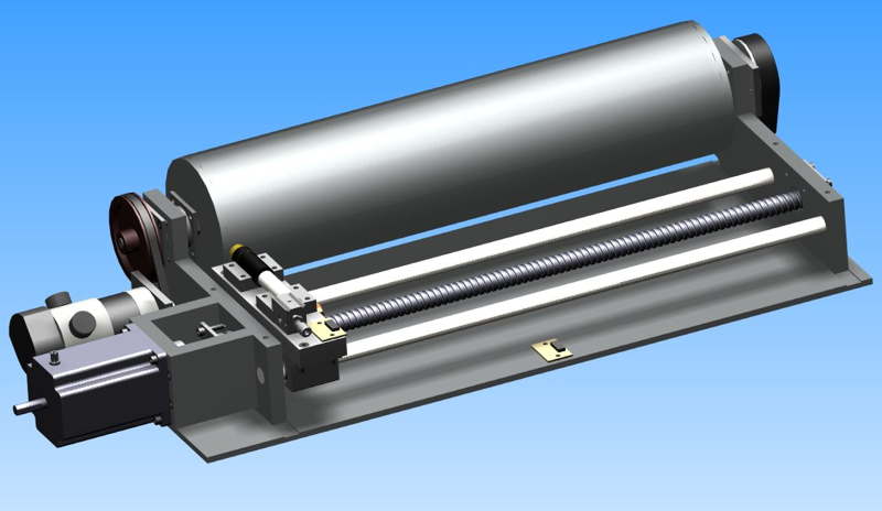
The CAD drawing of the photoplotter is shown below...
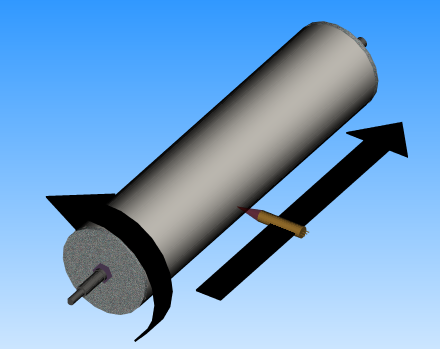
The photoplotter consists of a drum to which photo sensitive film is placed. This is an aluminium pipe with a steel axle running through the middle. On the left of the axle, back to back angular contact bearings allow the drum to spin and prevent any sideways movement. A timing pulley is used to connect a DC motor to the drum and gear it down to increase the motor torque. On the right hand side of the drum is an incremental encoder that locates the drum position so that the laser pulses can be fired at the correct time, generating the x-axis output. The encoder output is also used by the motor speed controller to keep it at a constant velocity.
In front of the drum are the guide rails on which the laser carriage runs back and forth. It is driven by a precision ground ballscrew with a 5mm pitch. The stepper motor, directly couple to the ballscrew on the left, turns the screw in small steps. This allows precision movement of the laser head in the y-axis.
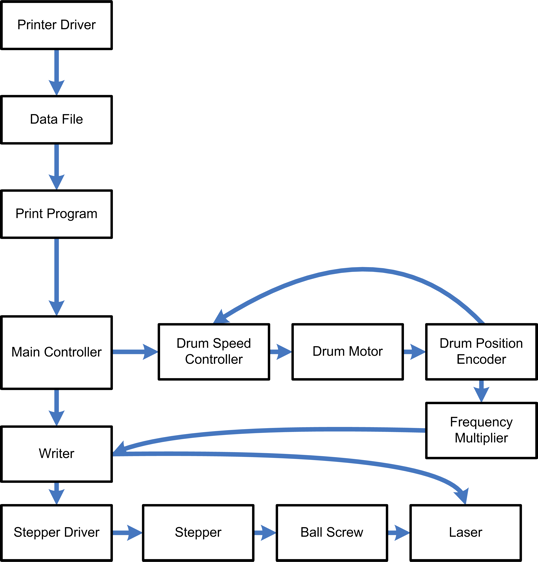
A more general view of the photoplotter are shown below. This includes the non-mechanical parts. The boxes link to more details.
Laser Carriage Drive Stepper
The stepper motor and driver were found on ebay. It is a Vexta 5 phase stepper motor and controller. The controller has a programmable stepping rate of from 500 to 125,000 steps per revolution. This keeps things flexible when deciding on the final resolution. The motor is connected to the ballscrew using an oldham style coupling purchased from RS Components.
Drum Drive Motor
The original plan was to use a brushless DC motor from and R/C model to drive the stepper. Part of the plan was to develop a brushless controller for it. The brushless controller project is still on going, but is taking too much time, so a standard DC motor is being used.
The first motor selected was a "hobby" style 12 volt DC motor from Jaycar (part number YM-2770). This is a fine motor for the purpose. The timing pulleys I purchased from SDP/SI fit the shaft perfectly. The only problem was that it was a 12vdc motor, and I have a 24vdc power supply (24v is required for the stepper motor). So, it was decided to replace the motor with a 24v motor.
The new motor is a 24vdc servo motor. This one I found on Oz ebay. I've only tested it a little, but it seems to work fine. I think it is rated at 24W power output, which is more than enough. This is still to be installed.
Drum Drive Pulley
The pulley and timing belt were purchased from SDP/SI. Recently I have found local Oz suppliers of these parts, so I will buy locally in the future (as long as the price is comparable). I'm using MXL size timing belts and pulleys. The belt is 6mm. Currently I have a 100 tooth plastic pulley on the drum, and a 10 tooth plastic pulley on the motor. The motor shaft is a bit short, and when the belt is tensioned, the pulley flexes. When I replace the motor, I will also replace the pulley with a 20 tooth one. The longer shaft on the new motor should resist flexing. The new motor shaft is 6mm in diameter, compared to 3.1mm on the old one.
Back to Back angular contact bearings
Bearings are used on the axel and the ballscrew to keep things turning smoothly. Standard deep row ball bearings are used on the right hand side of the drum and ballscrew. On the left hand side, back to back angular bearings are used to provide the rotation and prevent axial movement.
Drum
The drum has caused me a bit of grief. It comprises an aluminium pipe, with two end caps, an axle through the middle, and a couple of nuts on the ends holding it together. An exploded drawing is shown below...
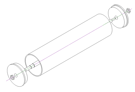
I carefully machined the axle and the drum ends. They were all nice and concentric. I then assembled the drum, using a bit of JB Weld epoxy to encourage to stay together, and tightened the lock nuts. After the glue had dried, I put the assembled drum back on the lathe to take a final light cut, and found the drum was off centre by more than 1mm. I machined it regardless until the outside of the drum was concentric with the axle. When the drum was assembled with the photoplotter, I could see immediately there was an issue as when the drum was spinning, it would always stop and rock back to the same spot. When I finally connected the drum motor and spun it at 600rpm, it start vibrating terribly. The drum needs to be recreated.
Incremental Encoder
The incremental encoder is attached to the axle on the right hand side of the photoplotter. It is a US Digital E6S 2500 CPR encoder. The encoder contains a disk with small precise lines inscribed on it. An optical sensor detects when the disk is moving and generates a series of pulses. This encoder generates 2500 pulses per revolution. There is also an "Index" pulse which only pulses once per revolution. This single pulse is used to identify the start of the page.
Guide rail
Two 1/2" precision hardened steel rods form the rail that the laser carriage assembly travels along. The rails are held in place by the photoplotter chasis sides. The rail retaining holes where precision bored to get the exact distance apart.
Two linear bearing pillow blocks run on rails. They contain a row of ball bearings that keep them moving along the shaft with no sideways play.
Again, these parts were found on ebay.
Ballscrew
Hurray for ebay! Yep, I got the ballscrew there too. A NSK WFA1405. 14mm diameter, 5mm pitch, precision ground ball screw.
The width of the photoplotter was decided by the lenhth of the ballscrew as I was too scared to try and machine it. Apart from being hardened in places, I didn't want to damage it.
The ball nut on the screw is bolted to the laser carriage.
Laser carriage assembly
This is the little table that runs back and forth along the drum. The laser will be mounted to this. It has been designed so when the laser is installed, it is at the axial height of the drum (ie at 90° to the surface)
Print Driver
The print driver was surprisingly easy to create. Windows (I'm currently using XP) supports generic raster, postscript and plotter printing devices. By using a configuration file (the GPD file) I could easily generate a raster image of what ever was being printed. All I had to do was specify the resolution of the photoplotter (current guess is 4000dpi), and specify how to format the output data, documented below.
Details of the windows printer drivers can be found online in the
Windows DDK (free download). My printer driver can be downloaded here
![]() .
.
Data File
The format of the printer driver output is simple. It comprises a header packet, followed by many line packets, and terminated by an end of data packet...
Header
| Byte | 0 | 1 | 2 | 3 | 4 | 5 |
| Content | 1 | Width MSB | Width LSB | Height MSB | Height LSB | Negative Flag |
Line Data
| Byte | 0 | 1 | 2 | 3... |
| Content | 2 | Length in Bytes MSB | Length in Bytes LSB | Data.... |
End
| Byte | 0 |
| Content | 3 |
The format isn't intelligent, specifically, there is no compression. Lines with no data have a length of zero, and only the actual data on a line is sent (no trailing empty space). Even though the images are monochrome, the 4000dpi will still generate a file 30MB file for a small PCB.
Print Program
Although it was simple produce the output, it was a little more tricky working out how to send it to the print device. So I took the easy way out and wrote a separate program to download the data to the photoplotter. This also gave me the opportunity to do some manipulation to the image: mirror, negative, resize print area, and reposition the image. The image can then be resaved, or sent to the photoplotter.
The print program uses the zmodem protocol to communicate to the photoplotter. This was just a quick and dirty way to implement the data transfer in a reliable fashion. This may be changed in the future.
Below is a screen shot of the print program with an image of the PCB...
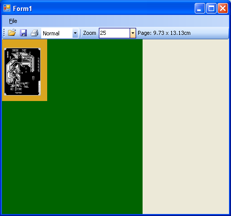
The image of the PCB, the black on white, is the image that is to be printed. The gold area represents the print area that will be sent to the photoplotter. The green area is the maximum size a print job may consume.
Normally a print job will create a print area the size of the selected output page, eg an A4 page. To speed up the print time, the image should be moved to the top left corner, and the print area reduced.
The source code to the print program is here ![]() .
.
Mainboard
Main Controller
The main control PCB contains to microcontrollers. The "Main Controller", and the writer.
The main controller interfaces to the PC and print program via USB. It uses a DLP design DLP-USB245M parallel interface USB module. It writes commands to a CY7C466A-10JC, 64k FIFO memory buffer. This chip implements a queue in hardware. It contains a 9bit data input bus, and a 9bit output data bus. This allows the main controller to write data into the FIFO, while the writer is reading it - Mmmmm, parallel processing! Well, more like buffering. The main controller will receive and store a complete line of data into the FIFO before signalling the writer to write. Then, while the writer writes, the next line is uploaded. The FIFO chip manages queue full/empty statuses.
The main controller is also responsible for telling the drum speed controller to start, and will wait until it is up to speed.
The component has an RS232 interface for debugging.
It is possible that this design is overkill. It may have been possible for a single chip to do all the work, as the USB interface chip has a 128 byte buffer and parallel interface which may have been enough.
Writer
The writer is responsible for output lines of data and moving the laser carriage.
When the writer first starts, it will home the laser carriage, and wait for commands.
The main controller will spin up the drum and start giving the writer new commands.
Lines of length zero will immediately step to the next line.
A non-zero line, will wait for the index pulse, indicating the start of the page. Then, at each of the frequency multiplied pulses, the writer will either turn on, or turn off the laser depending on the data bits. At the end of the line, it will turn of the laser and move to the next line. If the processing is fast enough, it should be able to move to the next line, and receive the first bit of data before the index pulse comes around again.
This continues until all the data is written.
The schematic for the mainboard is shown below. (click on it to view the pdf).
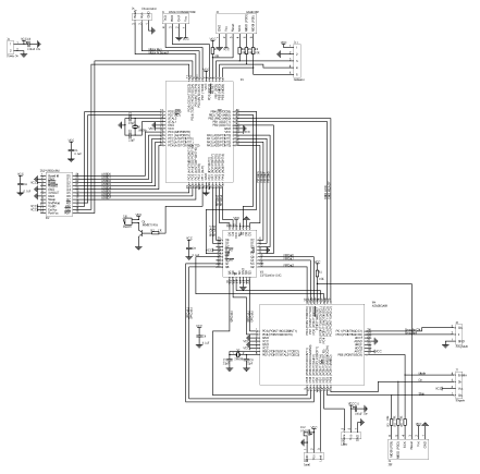
There are two firmware files for the mainboard. One for the Atmega162, the interfacing chip, and one for the Atmega88 which does the writing.
The interface firmware can be downloaded here ![]() .
.
The writing firmware can be downloaded here ![]() .
.
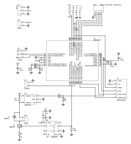
Drum Speed Controller
This is a simple, one direction, DC speed controller. Its interface is one "Run" bit, and it returns a "Ready" bit, when it is up to speed. The speed is selected using a rotary switch to select one of 16 predefined speeds. If a different speed is required, the microcontroller must be reprogrammed.
The speed control algorithm uses a simple PID loop. The speed of the motor is determined by monitoring one of the encoder channels, and counting pulses to determine the speed.
The schematic is shown below. (Click on it for the pdf) Note that the latest version uses a IXDN404PI in place of the MAX4427 because it now runs off 24 volts and the MAX4427 won't work above 18 volts.
The firmware for the controller can be downloaded here ![]() .
.
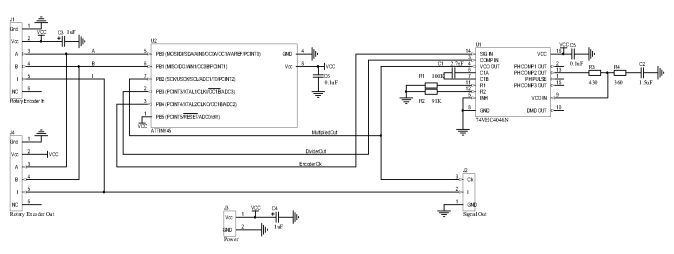
Frequency Multiplier
To be able to get the 4000dpi resolution on the drum from the 2500cpr encoder, a frequency multiplier is used. This is a simple circuit based on the schematics found in the datasheets for the CD4046 phased-locked loop chip.
Apart from the 4046, a ATTINY45 is also used on this component. The frequency multiplier takes the encoder A and B channels, converts that to a x2 pulse feed for the 4046. The 4046 then multiplies the frequency, then loops it back to the ATTINY45 where it then divides the signal (by 10 at the moment), and then sends it back to 4046 to complete the loop. This appears to work fine with a drum speed of 1Hz, but hasn't been tested at 10Hz yet. There may be issues with latency. If this is the case, the encoder decoding can be replaced with a logic XOR gate, leaving the ATTINY45 as a dedicated divider. With the way the 4046 works (using resistors and capacitors to tune it for certain frequencies), I will need a new version of this for higher speeds.
This part of the project has been a nightmare. Usually I get components working on a breadboard then make the PCB. With this project, once I got it to the PCB, it just would work. Then I switched back to the bread board and it would only occasionally work. I think the problem is the CD4046 is a very sensitive chip. Wiring it up on the breadboard while it is powered up will fry the chip. I have a stack of about 5 that no longer work.
Here's the schematic of the frequency multiplier.
The firmware for the Attiny45 can be downloaded here ![]() .
.
Laser
There will be a laser and some optics. Unfortunately I haven't got any further than that. The laser needs to pulse at the required rate (currently a maximum of 500kHz), and output enough energy to activate the light sensitive film, what ever that value is.
Progress
Below is a photo of the photoplotter in its current state....
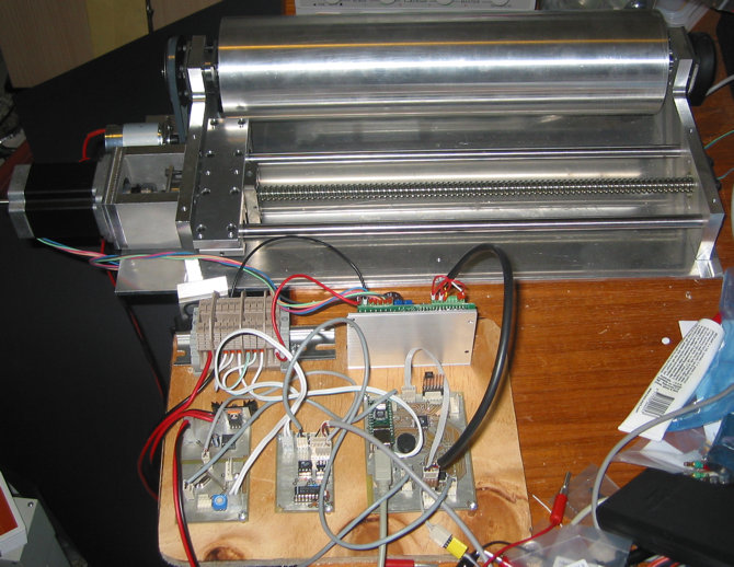
Currently on the todo list is...
- Replace 12v motor with 24v
- Wire up laser
- Rebuild Drum
- Paint shinny bits matt black
- Make laser mount
- Make new frequency multiplier for 10Hz drum speed
- Performance tweaking - make sure the software can keep up at high speed.
- Box the electronics.
- Remove the LEDs - whose dumb idea was it to put lots of flashing LEDs everywhere next to light sensitive film.