Serial Mon
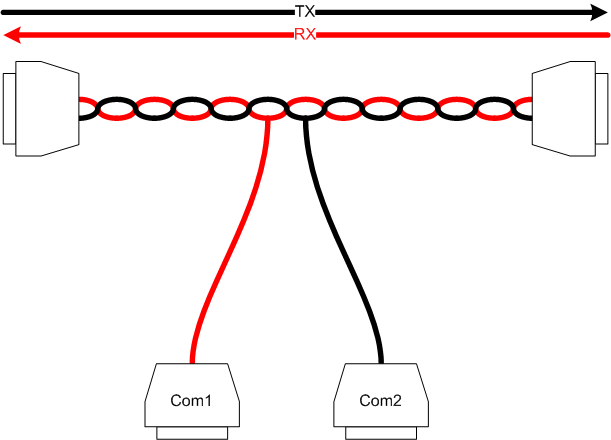
Many, many years ago when I did RS232 communications programming, the way to debug a communications stream was to use Ray's Serial Port Monitor program and his octopus cable. The software was DOS only and worked directly with the internal RS232 chips of the PC. The octopus cable split the TX and RX wires of the line into the RX pins on two different serial lines. Here's a picture.
Here's a link to one someone else has written.
Unlike the Windows Serial Port spy software, this actually looks at what is on the line, not just what is appearing at the end. It also doesn't require one end to be on a windows pc, which was my requirement. I needed this to spy on the RS232 communications between the console and motor of my treadmill. Unfortuantely, it requires a PC with 2 serial ports, which none of my PCs (or laptop) had. The easiest solution is just to get another serial port. But where's the fun in that.
Design
My initial design was simple. An FTDI FT232R USB to serial chip, talking to an Atmega48 microcontroller running at 20MHz. Unfortunately this means the serial interface would be used for communication between the USB chip and the microcontroller. No problem, the serial port monitoring will be done in software.
I wanted to support TTL serial and RS232 serial, so some logic gates and an RS232 level convert will be needed.
Instead of putting a programming port on the board, I decided to use the FT232R general purpose IO pins to program the chip. I will be able to program the chip without special hardware. And I'll be able to reprogram it to do different things! Which is when I thought this would make a good general purpose tool for all communications. My design will including support for RS232, RS232 TTL, SPI, and I2C/TWI.
The schematic of the latest version is shown below...
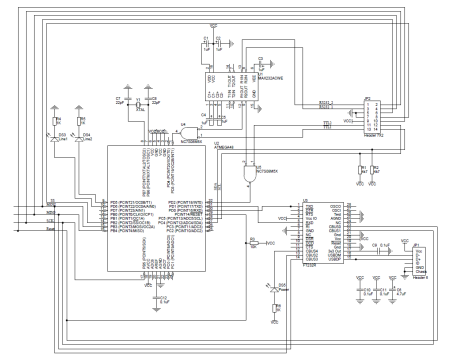
This is version 3 of the schematic. I'm currently using version 2. The only difference is the connections for the external ports. Version 3 has SS and Reset outputs, as well as Vcc output, useful for when using TWI. Version 2 was hacked to provide these lines.
Points of interest on the schematic...
- Pins CBUS0, CBUS1, CBUS2 and CBUS3 of the FTDI are connected to the Reset, SCK, MOSI and MISO lines of the microcontroller. The same microcontroller lines are available on the external interface, so the chip can be programmed from there. I did this because programming via the CBUS pins can take 5 minutes. This is only an issue the first time, because after the boot loader is installed, reprogramming will only take seconds.
- The RS232 and RS232 TTL inputs enter via two AND gates. I haven't tested this yet as I have only used RS232 TTL.
- The TWI/I2C lines have 4k7Ω pullups.
The untested version 3 pcb layout is shown below. Click on it to get the pdf artwork.
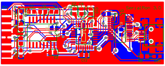
These are the gerber files that I used at www.batchpcb.com (I'm still waiting for delivery). I normally make my PCBs at home, but I can't do buried vias (links between board layers obscured by components) which I needed to make a cool little board. If you use them, you can ignore the warnings that come up when you upload them to BatchPCB.
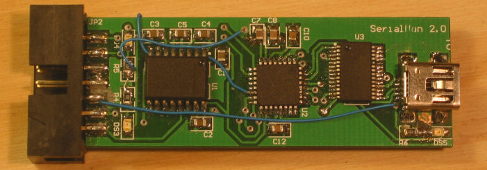
Here's a picture of the hacked v2 board. The blue wires fixed up some of the problems.
Software
General Programming
The first software written was to interface to the ftdi chip and program the AVR microcontroller. This was done using C#. The code interfaces to the ftdi chip using the D2XX interface because we need to access the low level features; predominately the CBUS interface.
The application must access the ftdi chip's CBUS interface to do the bit bang programming of the microcontroller. The program is capable of programming the microcontroller's fuses, program memory, boot memory and eeprom.
The program is a quick and dirty application. It was written to just load the initial firmware. It only programs an atmega168. It only sets the fuses to match the requirements of this application. It will only program the microcontroller with a firmware file located at D:\Projects\Tools\SerialMon\Source\SerialMon2\main.hex in Intel hex format. That said, it won't take much work to make it do what you want. It's more useful if you think of it as a library or sample code.
The code is here ![]() .
.
This application doesn't have the bootloader code in it yet. Check out the I2CHarness below for an example of the bootloader code (via XModem-CRC).
Serial Monitor
This was the main reason for creating the serial monitor device. An application to monitor a serial communications line.
The application features...
- Baud/Bits/Parity/Stop bits configurable per line.
- Any baud rate imaginable.
- Auto-baud tries to detect the baud rate on each line.
- Captured communications can be saved to a file and loaded back later.
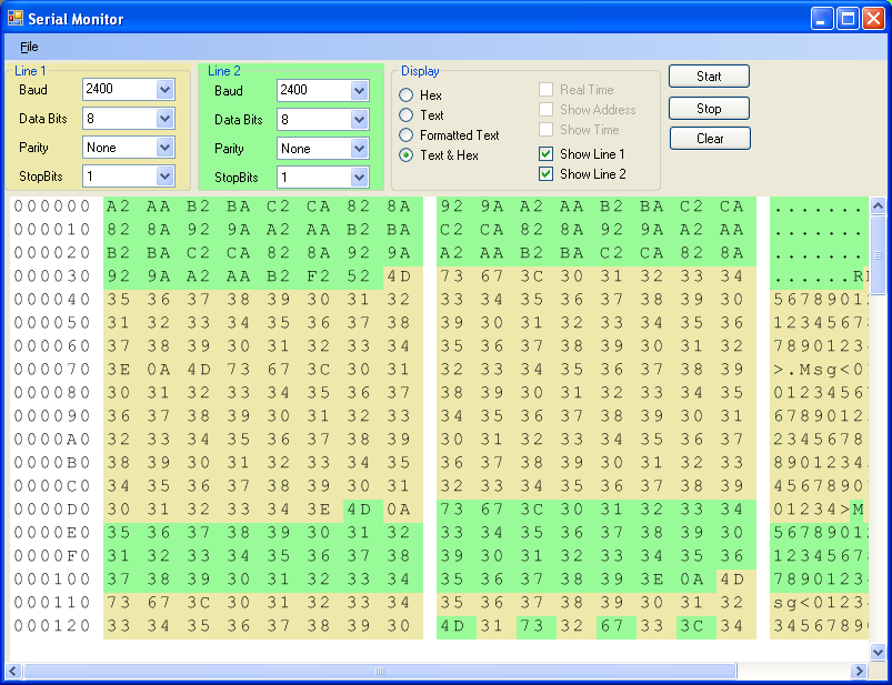
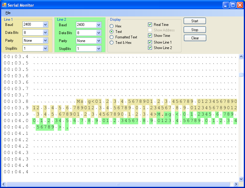
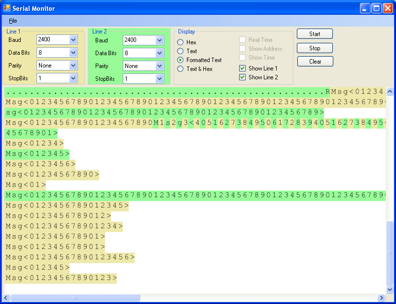
- Data can be displayed as Hex, Text, Formatted Text, or a combination Hex/Text.
- Data can be displayed in real time. That is, gaps representing time will be shown on the display.
- Display the address (offset from the beginning of the capture)
- Display time (time since the beginning of the capture)
Some screen shots of the application showing its different display modes follow...
Ah! I'd be a great salesman. OK, the client application does most of that. The firmware, however, is a bit dodgy. It's written in C, so not as fast as assembler would be. I started having problems getting the firmware to read two serial lines, do stop bit and parity check and return the data. I stripped out the functionality until it was just reading data. I only needed to monitor my treadmill which communicates at 2000 baud, so I stopped when I got there. I'll enhance the firmware when I get a project that demands more performance.
The firmware for serial port monitoring is here ![]() . It needs to
uploaded to the serialmon board. This firmware was written for
version 1, which didn't have the FTDI programming interface or a
bootloader.
. It needs to
uploaded to the serialmon board. This firmware was written for
version 1, which didn't have the FTDI programming interface or a
bootloader.
The source for the client application is here ![]() .
.
I2C/TWI Interface
I plan to use the I2C interface for communication between the hardware components of my robot. The first component I built was the brushless dc servo controller. So I needed an I2C module for the serialmon board so I could communicate from the PC to servo controller.
The I2C Interface comprises two parts: the firmware, and a pc interface library. The library is written in C#.
The firmware is here ![]() .
.
The library is here ![]() .
It is made up of the I2C library, the ftdi library and a test harness.
Currently there is no separate build for each library; you need to build
the test harness. The test harness also includes the XModem code
to perform a bootloader upload.
.
It is made up of the I2C library, the ftdi library and a test harness.
Currently there is no separate build for each library; you need to build
the test harness. The test harness also includes the XModem code
to perform a bootloader upload.
The software library provides an interface to the serialmon I2C firmware. The I2C functionality can be accessed through the I2C library functions...
| Method | Description |
| I2C(FTDI.FTDIInterface ) | Constructor. Requires an open connection to the FTDI device. |
| QueryVersion | Queries the firmware version. This is an asynchronous command. The results will be returned as an event. |
| BootLoader | Invoke the bootloader. This command doesn't return anything. |
| ConfigureMaster( byte MasterBitRate, byte MasterPrescale, bool UseIntenalPullup, byte Timeout ) |
Configure the I2C master. The values MasterBitRate and MasterPrescale are from the atmegax8 documentation. Alternatively, call CalculateMasterBitrate to calculate these values. UseInternalPullup will use the internal bus pull-up resistors, which is superfluous, because there are bus pull-up resistors on the board. The timeout is the time to wait for a command response in ms. 0 for no timeout. |
| ConfigureSlave( byte SlaveAddress, bool HandleGeneralCall, bool UseInternalPullup, byte Timeout) |
Configure the I2C slave. SlaveAddress is the device's bus
address, 0-127. HandleGeneralCall means the slave should
handle a General Call (broadcast). UseInternalPullup will
use the internal bus pull-up resistors, which is superfluous,
because there are bus pull-up resistors on the board. The
timeout is the time to wait for a command response in ms.
0 for no timeout.
I2C Slave isn't really implemented. |
| SendData( byte address, params object[] data ) |
Send data to an I2C device. address is the address. data is a variable argument list of bytes or integers. |
| SendData( byte address, byte[] data) |
Send data to an I2C device. address is the address. data is an array of byte to send. |
| ReceiveData( byte address, byte nLen) |
Receive data from an I2C device. address is the address of the slave. nLen is the number of bytes to wait for. |
| event MessageError( byte nAddress, I2CStatusCode nCode) |
An error occurred. Address may be the last sender/receiver. The status code is the AVR status code, prettied up to be a C# enum. |
| event SendAck(byte nAddress) | Acknowledgement that a message was sent and accepted by an I2C node. |
| event ReceiveMsg( byte nAddress, byte[] data) |
Message received from an I2C node. |
The interface between the library and the firmware, over the USB ftdi serial communications is described below. It isn't necessary to know this if you use the library.
Each command to and from the serialmon board is in this format...
<Stx><Cmd><DataLen><Data><chksum>
where...
Stx - Message start code, 0xAA.
cmd - is the command, listed in the table below.
datalen - is the size of the data to follow
chksum - is the checksum calculated using the bytes from STX to the end of DATA inclusively, using the inbuilt avr crc16 routine _crc_ibutton_update.
| Command | Description |
| FE | QueryVersion |
| FF | Bootloader |
| 1 | ConfigureTWI |
| 2 | SendData |
| 3 | ReceiveData |
| 4 | BufferOverflow - message from serialmon to PC if the data in the last send command has filled the send buffer, or the last receive command has received more than what was expceted. |
It took a bit of mucking around to get the I2C interface working properly. The samples from the Atmel documentation seemed to fail and never recover properly. I had to search the 'net for other examples to get it working properly. Currently only the I2C master has been implemented.
SPI Interface
The RGB matrix project uses the SPI interface, so it would be handy to have an SPI module. Until I add one, it remains on the todo list.
Future Enhancements
Did I hear some say SPI? That needs to be added.
Also, the I2C Slave.
I could also probably use I2C monitoring, and SPI monitoring.
The general programming application needs to be tidied up and bootloader support needs to be added. It should be able to upload firmwares to serialmon to change its behaviour: monitor, I2C, SPI, etc, and tell you what is loaded. The communication protocol between the PC and board needs to be standardised.
The monitor firmware needs to be optimized. Maybe just debugged. I'm not sure I'll ever need to hack some RS232 again - the ISOBOT protocol is already published.