Mini-Z Track Timer
So what do you build after the track? The computerised timing system of course!
I've seen this done on other web sites, by using small laser modules to create timing beams across the track. A small flag is attached to the Mini-Z antenna which breaks the beam to record another lap.
My system is based around bits and pieces I could get from the local Jaycar and Dick Smith electronic stores. To interface the system to my computer I used the Jaycar kit number KC5230, which interfaces via the parallel port. It has 8 digital inputs, although I could only get 5 working (problems with programming the parallel port), and 8 outputs, which are clunky relays, but they do the job.
For the light source, I used the Jaycar laser modules (ST3115). Originally I just drilled 4 parallel holes in a block of wood to hold the lasers, but they were not aligned in parallel. Instead, I engineered small adjustable boxings for the lasers. Each has a horizontal and vertical adjusting bolt that allows the laser to be precisely aimed at the receiver.
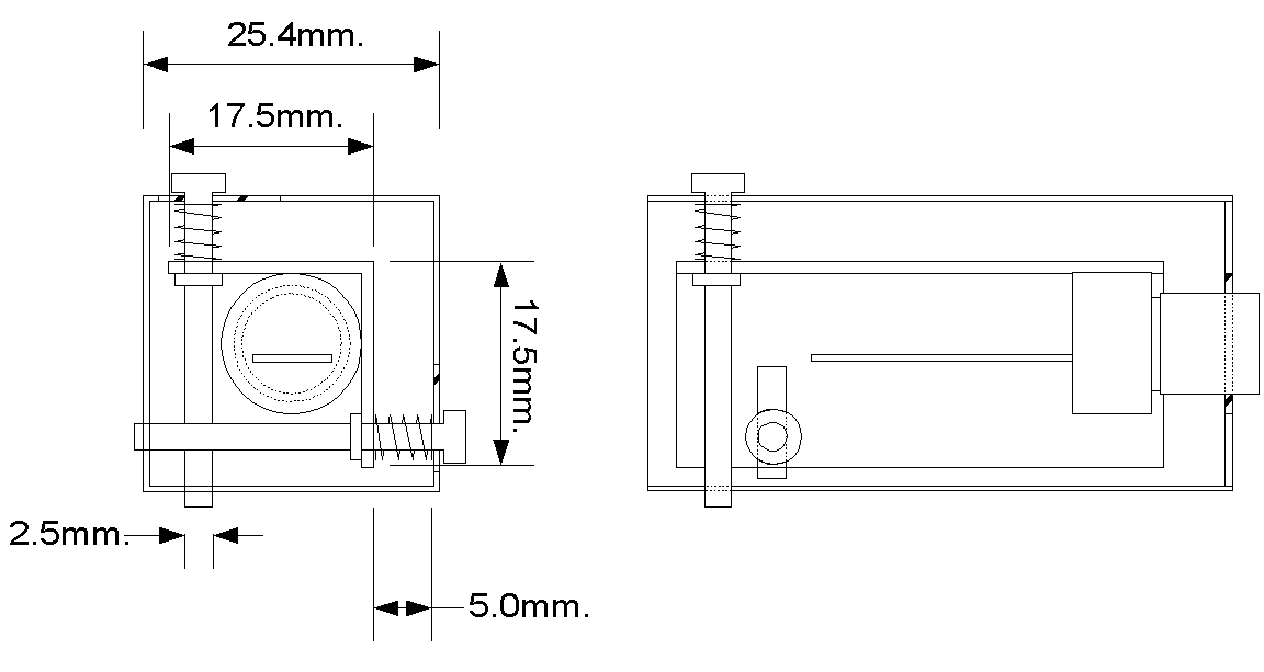
The following picture shows a close up of the laser mountings. Each laser is mounted in its own 1" square tube. A small angle plate is suspended inside the tube by two adjusting bolts at the back, and liquid gasket rubber on the front face. This is shown in the photo and technical illustration below.
![]()
The front view shows the laser modules protruding from their housings. They are held in place by the gasket rubber. This allows some flexiblity when the adjusting bolts are turned.
The housings are of different sizes so that when they are stacked, there is still access to the vertical adjusting bolts. Note that they are sized in pairs; the lower of the two pair's vertical bolt is adjusted through access holes in the upper one.
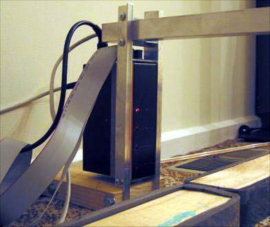
The set of four laser modules are mounted between two angle strips. They are long enough to hold the laser modules and to hold the cross member, which a) joins the transmitter (lasers) and receivers and holds them rigidly once aligned and b) holds the race start lights. The constructed laser tower is shown below.
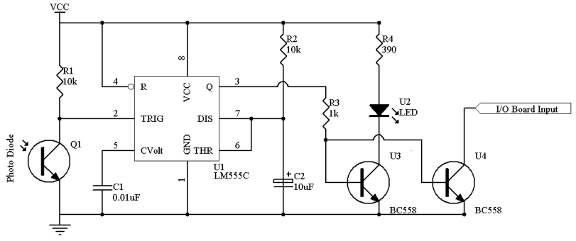
On the other end of the transmitter is the receiver. I used Darlington Photodiodes from Dick Smith (Z1956) to act as the receiver. The light trigger logic was bolstered by triggering a simple one shot circuit. This one shot, when triggered by the diode, will trigger the PC IO line and hold it for about 1 second. This is a bit of overkill, but it was done to ensure the PC did not miss a signal. To minimise the chance of the diode trigger off ambient light, the diode was mounted at the end of a ball point pen case. This is the schematic of the circuit I created.
All the electronics and pen case where built on a small vero board and mounted in a jiffy box. Here is the completed circuit board.
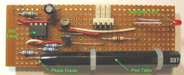
There are four of these inside the jiffy box.
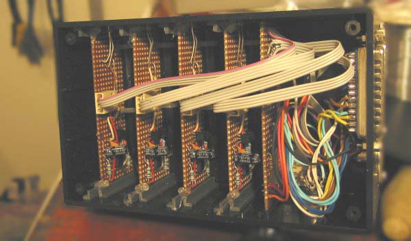
The completed box is shown below, again mounted between two angle strips to hold the cross beam.
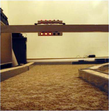
Of course it wouldn't be a real race track without proper start lights. So, by using 5 of the IO card's relay outputs, the lights were constructed on the cross beam. There are lights hanging below the beam, to give it an authentic F1 look, and another set above for the RC pilots. The completed system is shown below.
And to complete this little project, we needed some software to run the show. This was an opportunity to enter the world of .Net, so the program was written both C++, to provide low level access to the port data (using DriverLinx Port I/O), and C# to provide the visuals and logic. A photo of the screen is shown below.
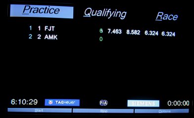
The Track Timer software was written to give an F1 feel, hence the logos. The layout was lifted from the F1 timing monitors as displayed in the DVD, "F1 Season 2000 in Review". There are some differences, for example, I don't record sector times. The columns are Position, Car Number, Driver Name, Gap to 1st (not shown), Gap to Previous (not shown), laps completed, last lap time, previous lap time, lap time before that, best lap time.
That is the end of phase 1. The big limitation of this system is that it has to be connected to a computer. So for phase 2, I want to create a stand alone, outside working system. This will give me the opportunity to enter the world of Microcontrollers. I can't wait!
Yes! The wait is over; TrackTimer Ex (that's Ex for External)