Mini-Z Track Timer Ex
The link off the home page says 3/10/2002, which technically was when I finished TrackTimer2, but I'm only getting around to writing this up now (07/2004).
TrackTimer1 was a simple project - a bit of electronics in the car detectors, a simple Parallel Port interface to the PC, and a bit of software to provide an F1 style display. I'm pretending the motivation for TrackTimer2 was a lap counter that could be used outside, but I really just wanted something else to work on, and I wanted to try a project using microcontrollers.
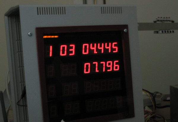
Here's an action shot of TrackTimerEx, showing Car 1 has completed 3 laps, with best lap time and last lap time. I think this shot was taken while still developing it because the sides of the box have not been placed.
Functionality
TrackTimerEx has the same functionality as TrackTimer, except that it is a standalone, portable unit. Also, it can only display numbers, and some pseudo words made up from the 7 Segment LED displays. It only has a buzzer so its sound is limited.
Schematic
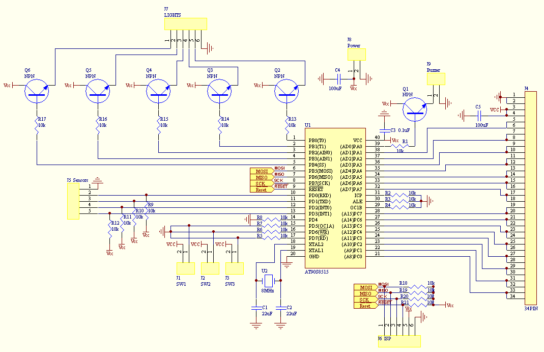
The circuit is based around the Atmel AT90S8515. All but 1 of the I/O pins have been used: 15 for the display multiplexing, 1 for the buzzer, 3 for the input switches, 4 for the track lap sensors, 5 for the gantry lights. 4 are dedicated to the ISP programming which could have also been used for other purposes.
As already mentioned, the display is multiplexed. There are a total of 32 display digits, each made of 7 segments and 1 decimal place. Hence there are 8x32, or 256 LEDs to control. The multiplexing is done by using 5 I/O pins to select the digit, and 8 I/O pins to select the segments. The 5 digit select lines are demultiplexed using 2, 74LS154 (not HC as shown in the schematic), 4-Line to 16-Line Decoder/Demultiplexer. The chip select function is contolled by the 5th bit, and transistor Q40.
The display is controlled by the microcontroller software. Each update cycle, a new digit is selected and the appropriate segments are lit. The displaying of the segments is controlled in the main loop of the software. All other functionality - timing, button presses - is controlled in the interrupt routines.
A 74LS139, 1 of 4 Decoder/Demultiplexer, is also used to display the mode lights. These are used to display whether the unit is running in Practice, Qualifying, Race, or Setup modes.
The project is broken up into 2 schematics: the controller and the display. This is also how it was fabricated, split into 2 boards, connected by a 34 pin IDC connector and cable.
 |
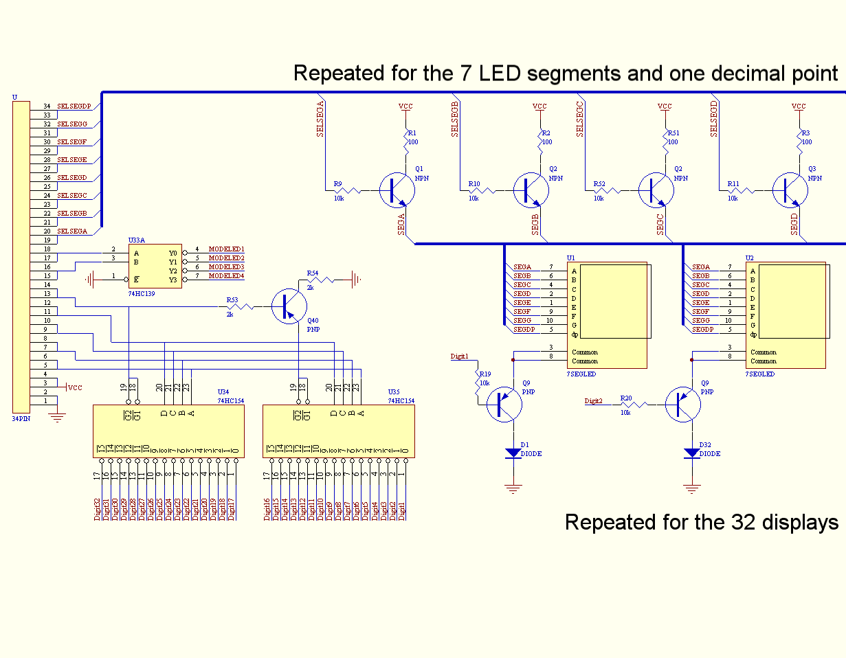 |
| The microcontroller schematic contains the microcontroller, some support components, and lots of plugs and sockets to other parts of the project. | Here's a snippet of the schematic for the display. The multiplexing works by selecting which digit, Digit1-32, is going to be displayed, and which segments are going to be lit, SELSEGA-F. |
Construction
For some silly reason, I decided that I would make the whole thing using bread boards. I think I was intimidated by the size of the PCB I'd have to make. I didn't realise the chore it would be to wire up all of the displays.
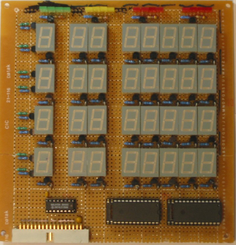
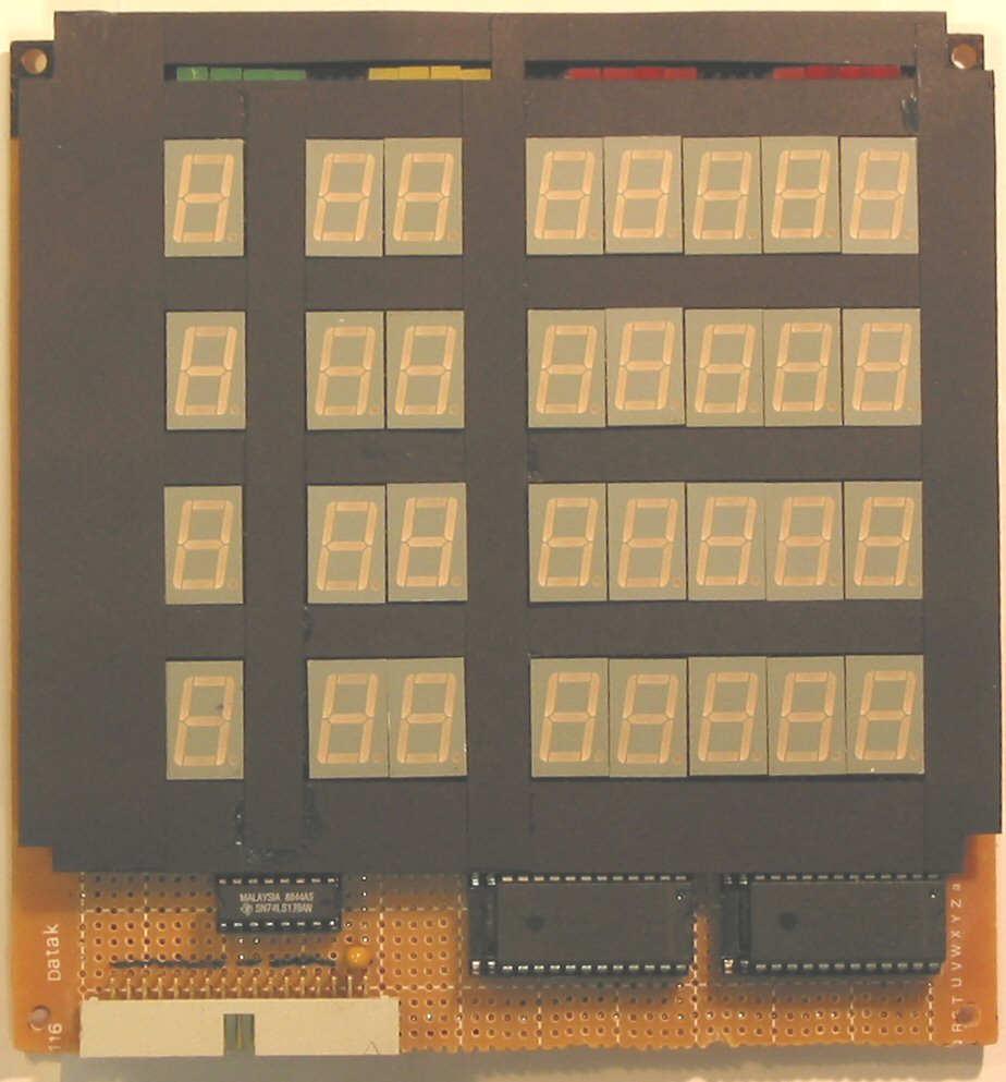
Here are the front and back shots of the display circuit board.
 |
 |
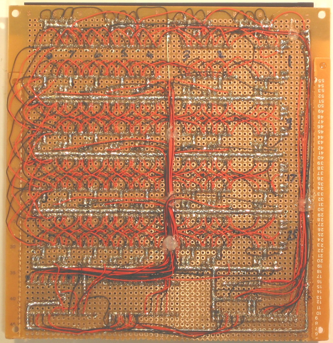 |
| The front of the display board. Display LEDs and components are on the top of the board. | The board with bits of black cardboard to hide the PCB and electronics underneath. | The display back. A monstrous bit of spaghetti wiring. This was all soldered up using wire wrap wire. The close up shows the donut style breadboard. |
The 7 segment LED displays were damn near impossible to source. I grabbed a couple from Jaycar, and their brightness was uneven. Then I tried Dick Smith. They had high intensity ones that had a consistent high brightness. The only problem was that each store around me only had a few each. The sales guy said he could order them in from other stores, but I'd have to pay the courier costs. Yeah right. So I drove around to about 7 stores to find the 32 displays. Next time, I'll just order them over the internet, which was not something that was really viable back when I did this - either outrageously expensive - cost, delivery, import duties - or they didn't ship internationally. Thankfully this is not an issue anymore, as I regularly get stuff from Digikey, and Mouser, and there are a couple of locals, Rockby, and the expensive RS Components (but they do have a big range).
The segment select transistors were placed on the left hand side of the board (from the front), hidden under the cardboard. The display select transistors and resistors are under each display, also hidden by the cardboard. The decoder/demultiplexers are at the bottom. The chip select transistor was stealthily hidden under right most decoder chip in the IC socket.
The back of the display shows what an effort it was to wire this up. Like anodes of the display segments are all wired up together, then to the transistor switch, then to the socket. Each digit is wired to an output of a decoder IC. The whole process was made simpler by using a Jig to create pre-bent, pre-stripped wire segments. The jig was nothing more than a small block of wood with nails zig-zagged along it, spaced out to match the pins on the bread board. A soldering iron was used to melt off the insulation at the solder points. Also note the dollops of hot melt glue to keep the wires from moving.
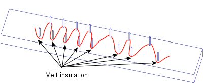 |
| The wire twisting jig. |
The microcontrolled board is quite boring in comparison. It has the main IC and a few support components soldered in.
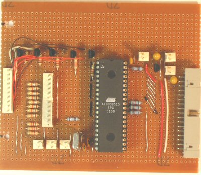 |
| The microcontroller board used a different style bread board, with single tracks that run horizontally on the image above. That's why there wire links on top of the board. |
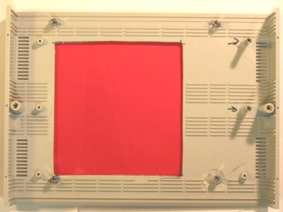
The project was packaged up into a neat project box. A piece of red perspex was used to cover the window to the display. This is shown below. Note the spacers glued to the inside of the box. The are 15mm long, 3mm tapped spacers, screwed in from the front, and glued to prevent them from moving. This is ugly, and on the "to do" list if I ever rebuild.
|
|
|
The inside of the mounting box showing the red perspex window. This was glued to the outside. |
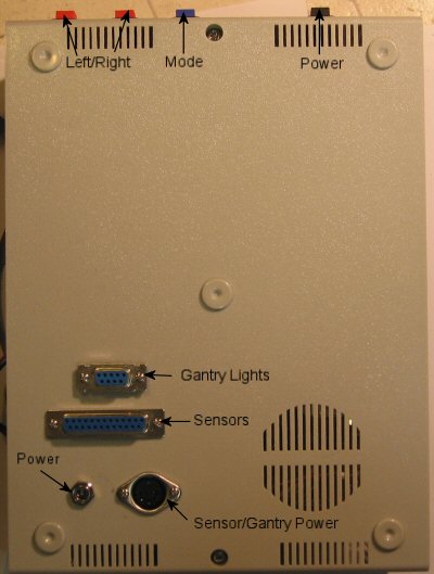 |
| This is the back of the box showing external connectors. |
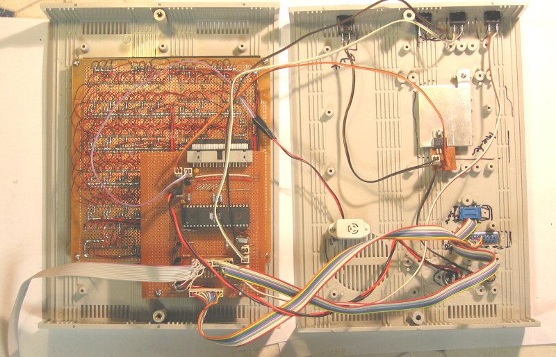 |
| Here's the internal placement of the components. The display and controller circuit boards are stacked together. The split design of the box made it easy to work with. This shot shows the ISP programming cable running off to the lower left. |
Version 2.0...
I am pretty happy with the way this project work out, but there are a few things I'd do differently...
- Firstly, I will never again breadboard a project that big. PCBs are the way to go, although I have never produced anything that big, nor anything double sided (I'm pretty sure the display will need to be double sided.
- Find better display LEDs. Those 7 segment LEDs are so '70s. There are much cooler display technologies - dot matrix, alphanumeric in LCD, LED, VFD, and maybe even OLED.
There are a few things that could be changed for version 2.0, which will probably never exist...
- Better sound output, using PWM, or something, so a better starting horn, pit entrance bell, and podium music
- Improve the lap timer sensor. It is badly effected by background light. It really only works inside, and with the blinds closed. Maybe a modulated signal.
- Infrared remote control to start/stop races.
- A better display and interface to display racer's names, and more driving statistics.