DCC Servo Decoder
I built the servo decoder to switch my hand laid turnouts. I looked at the standard solutions, such as the tortoise, but they were enormous for a z-scale layout. I planned to use ultra-miniature rc servos to do the switching.
Functionality
- Drive up to 8 RC servos to simulate the opening and closing of a turnout.
- Provide outputs for each servo to control the signal
lights surrounding the turnout.
- Support for individual, bicolour and tricolour LEDs
- Controlled by DCC
- Supports configuration variables with acknowledgement
- Accessory Address Lo
- Accessory Address Hi
- Configuration byte
- Interactive Programming Address
- Enable Interactive Servo
- And for each servo,
- Servo Min position
- Servo Max position
- Servo switching time
- Servo Configuration byte
- Support a simulated "run" where adjusting the accessory "speed" sets the min/max positions of the turn out.
Design
The electronics design is quite simple. The schematic is shown below (click on it for the pdf)
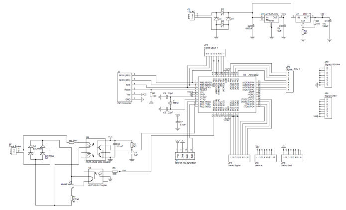
Things of interest...
- U4 is a high speed opto-coupler used to read the signal transmitted in the track lines.
- U5 and Q1 are used to load the track (draw more than ?mA) . This is how the DCC accessory acknowledges commands.
- J4, is the RS232 TTL connector is for debug.
- J1 provides power for the module. I prefer a separate supply, rather than using the track power, but the track power can be used here.
- U1 provides 5v power for the the microcontroller.
- U2 provides adjustable power for the servos. This is currently set to 5.75v.
- JP5, JP6, JP7 provides drive for 8 servos, a signal wire, plus power and ground.
- JP1, JP2, JP3, JP4 provides the drive for the signalling LEDs, an open signal, a closed signal, power and ground.
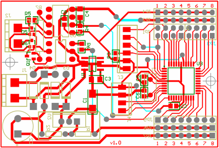
The PCB is here.
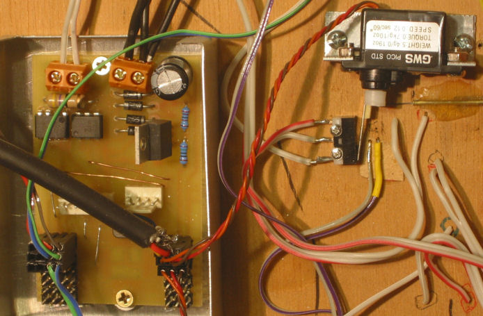
Here's an action shot of the PCB, wired up to 3 turnouts and signal LEDs. This is from my Test Layout.
Firmware
The important interfacing is done via interrupts.
The DCC input signal is picked up and decoded in the External Interrupt 0 handler. The interrupt triggers on any change, so the interrupt handler is called twice for each bit. Each transition is timed using 16bit Timer2. A short time is a 1. A long time is a 0. The time is checked to fit in a min/max range for each of 0 and 1. If the time falls outside this range, it is an error and the packet is discarded. A completed packet is stored in an array and a global flag is set to let the main loop know to process it.
Timer 0 fires every 2.5ms. This is to start a new servo output. Because the servo signal only lasts 2ms and is repeated every 20ms, we can service all 8 servos sequentially in 20ms, every 2.5ms. The interrupt also updates the position of any servos in motion every 1/10th of a second.
The servo pulse is started in the timer 0 interrupt by starting the timer 1 counter and outputting a value to the servo signal line. The output compare register is used to time the servo pulse. When the output compare interrupt triggers, the pulse is set to 0. This is not a good way of doing this because delays to the interrupt (for example, it is busy processing another interrupt), can cause jitter. A better way would be to use the output compare feature to set the signal to 0, but there are not 8 lines that do that.
The main loop is responsible for processing any packets that have been received from the DCC bus. This include CV changes, and operation changes. Opening and closing the turnouts is initiated by the main loop. The main loop updates the signalling LEDs.
The source for the firmware can be found here
![]() .
I must apologise for this code. It hasn't been touched for
3 years, lacks comments, and it's full of magic numbers and
debug. And I don't think it compiles, although I think
they are only issues with header files.
.
I must apologise for this code. It hasn't been touched for
3 years, lacks comments, and it's full of magic numbers and
debug. And I don't think it compiles, although I think
they are only issues with header files.
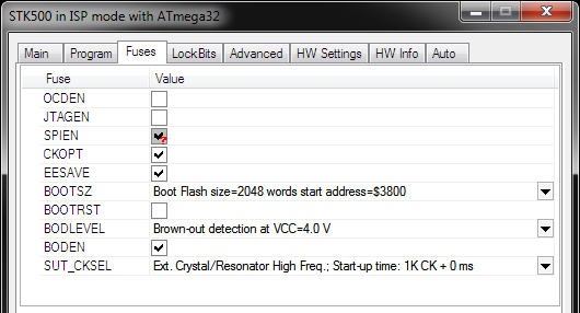
The source code is compiled with winavr although any gcc avr distribution should work.
I program the device and the fuses using AVRStudio 4 and an AVRISP clone. The fuses are set to...
Interface
The interface to the Servo Decode is a standard DCC Accessory (as far as I could interpret the standard).
The device is configured via configuration variables. These are listed below...
| CV | Description |
| 513 | Accessory Address LSB |
| 514 | Accessory Address MSB |
| 515 | Configuration byte. Currently none of the bits are used. |
| 545 | Servo 1 min position. The position the servo should move to when the turnout is closed. |
| 546 | Servo 1 max position. The position the servo should move to when the turnout is open. |
| 547 | Servo 1 switch time. The time, in tenths of a second, that it takes the turnout to close. |
| 548 | Servo 1 configuration byte. Bit 0 - Reverse turnout open/close direction. Bit 1 - Reverse the LED outputs. Bit 2 - LED is a tricolour LED. |
| 549 | Servo 2 min position. The position the servo should move to when the turnout is closed. |
| 550 | Servo 2 max position. The position the servo should move to when the turnout is open. |
| 551 | Servo 2 switch time. The time, in tenths of a second, that it takes the turnout to close. |
| 552 | Servo 2 configuration byte. Bit 0 - Reverse turnout open/close direction. Bit 1 - Reverse the LED outputs. Bit 2 - LED is a tricolour LED. |
| 553 | Servo 3 min position. The position the servo should move to when the turnout is closed. |
| 554 | Servo 3 max position. The position the servo should move to when the turnout is open. |
| 555 | Servo 3 switch time. The time, in tenths of a second, that it takes the turnout to close. |
| 556 | Servo 3 configuration byte. Bit 0 - Reverse turnout open/close direction. Bit 1 - Reverse the LED outputs. Bit 2 - LED is a tricolour LED. |
| 557 | Servo 4 min position. The position the servo should move to when the turnout is closed. |
| 558 | Servo 4 max position. The position the servo should move to when the turnout is open. |
| 559 | Servo 4 switch time. The time, in tenths of a second, that it takes the turnout to close. |
| 560 | Servo 4 configuration byte. Bit 0 - Reverse turnout open/close direction. Bit 1 - Reverse the LED outputs. Bit 2 - LED is a tricolour LED. |
| 561 | Servo 5 min position. The position the servo should move to when the turnout is closed. |
| 562 | Servo 5 max position. The position the servo should move to when the turnout is open. |
| 563 | Servo 5 switch time. The time, in tenths of a second, that it takes the turnout to close. |
| 564 | Servo 5 configuration byte. Bit 0 - Reverse turnout open/close direction. Bit 1 - Reverse the LED outputs. Bit 2 - LED is a tricolour LED. |
| 565 | Servo 6 min position. The position the servo should move to when the turnout is closed. |
| 566 | Servo 6 max position. The position the servo should move to when the turnout is open. |
| 567 | Servo 6 switch time. The time, in tenths of a second, that it takes the turnout to close. |
| 568 | Servo 6 configuration byte. Bit 0 - Reverse turnout open/close direction. Bit 1 - Reverse the LED outputs. Bit 2 - LED is a tricolour LED. |
| 569 | Servo 7 min position. The position the servo should move to when the turnout is closed. |
| 570 | Servo 7 max position. The position the servo should move to when the turnout is open. |
| 571 | Servo 7 switch time. The time, in tenths of a second, that it takes the turnout to close. |
| 572 | Servo 7 configuration byte. Bit 0 - Reverse turnout open/close direction. Bit 1 - Reverse the LED outputs. Bit 2 - LED is a tricolour LED. |
| 573 | Servo 8 min position. The position the servo should move to when the turnout is closed. |
| 574 | Servo 8 max position. The position the servo should move to when the turnout is open. |
| 575 | Servo 8 switch time. The time, in tenths of a second, that it takes the turnout to close. |
| 576 | Servo 8 configuration byte. Bit 0 - Reverse turnout open/close direction. Bit 1 - Reverse the LED outputs. Bit 2 - LED is a tricolour LED. |
| 577 | Interactive programming address. |
| 578 | Enable Interactive servo. When this variable is set to non-zero, the accessory decoder will start treating the accessory as a locomotive, listening for 7-bit speed commands on the address specified in CV577. If a speed is detected, it is used to set the position of the servo arm. The servo is selected by the non-zero value of CV578 (this CV). If the turnout is open, the open value (max) is set. It the turnout is closed, the closed (min) value is set. The min/max values will only be stored when this CV, CV578 is set back to 0. |
The normal operation accessory decode packet is shown below...
{preamble} 0 10AAAAAA 0 1AAACDDD 0 EEEEEEEE 1
Bit C is used open and close a turnout. DDD is used to select a servo. The DCC specification suggests that accessory outputs are paired so that the lowest D bit selects the output, and the upper two D bits select 1 of 4 devices. I just use the whole 3 bits to select one of 8 devices. I don't have a commercial DCC controller so I can't confirm this works elsewhere.
Wiring
Here's a diagram of the wiring options...
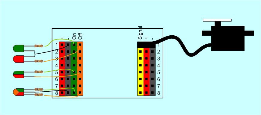
Servos are easy. They just plug in.
There are many signalling options...
- No signalling
- Separate On/Off LEDs (where on is an open turnout, and off is a closed turnout)
- Bicolour LEDs. These LEDs have 2 legs: power them in one direction and they show one colour. Reverse the polarity and they show another colour.
- Tricolour LEDs. These are effectively 2 LEDs in the one body. One leg for each colour and a common ground (cathode). Three colour combinations can be made by lighting LED A, LED B, or both A and B.
- Only one LED on the on or off lines.
LEDs can also be connected in parallel to have more lights, or redundant signals.
A current limiting resistor must be installed. The LEDs are driven directly from the microcontroller pins. They must be limited to 20mA each, according to the Atmel spec.
Next Version
A few improvements are necessary...
- Moving the servo arm is very noisy (audible). I'd like to try changing the voltage on the servos to see if lowering it would make a difference. Some micro servos work down to 3.0 volts.
- The servos seem very susceptible to electrical noise. I reduced this by putting the PCB in a metal box, and using shielded servo cables. I need to look into this.
- A pretty LED or two to show the device is powered up, and flash it to acknowledge commands.
- Servos are usually highly geared, such that there is no need to continue providing power to hold the position. Maybe just removing the positioning signal will work.
- Rethink how to generate the servo timing signals. The timing seems to be a bit in accurate making the servos jiggle - maybe using a timer output and a 1-in-8 decoder.