Test Layout
Given that I'm probably never going to finalise a track layout, I put together a couple of test layouts so I could begin playing.
Layout 1
I needed the first layout so I could test my home made DCC controller. The layout was constrained to the size of scrap plywood I had lying around.
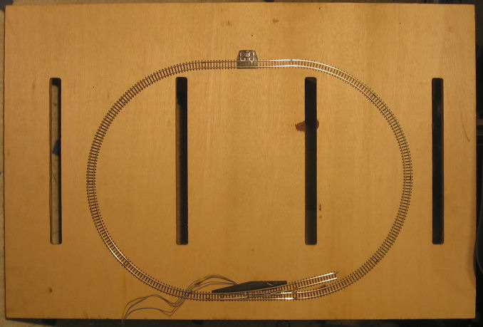
The board is 60x40cm. In a previous life it was router jig to cut the frame of my long stock storage rack - hence the slots cut into it.
The track is stock Märklin Z-Scale track pieces. The size of the board and the placement of the slots made it difficult to put a larger track on it. But that wasn't important. The track was there just to test my DCC controller and power supply.
As you can see, the track is a simple loop with one turnout. I'm glad I added the turnout because it showed me how sensitive they were. Trains derail very easily going through them. I also had problems with connections between tracks. Even though the track is nailed down, and there are track joiners everywhere, I still get back connections. To do this properly, the connections will need to be soldered.
After a bit more internet search to find out if this is a common problem, I decided in the future to handlay all tracks.
Layout 2
This is my second test layout. It is on a larger board, 90x45cm. Although not much bigger, it was able to hold a lot more track.
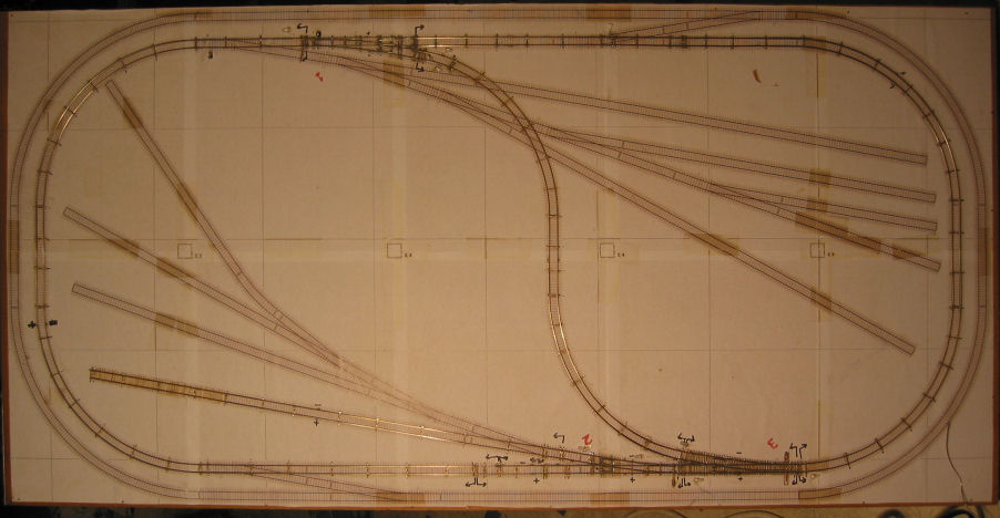
The track was designed using 3rd Planit and printed onto 10 A3 sheets of paper. This is then glued to the board and the track is hand laid on top of that. Only part of the track has been implemented. (Hover over the picture with the mouse to highlight the completed bits). There are 3 turnouts and a reversing loop. These are the bits I needed to start building some of the electronics. There are quite a few turnouts that haven't been created, not to mention some nasty crossovers that may never see light of day (the track that passes through the reversing loop).
The next picture is the underside. It's surprisingly messy for such a simple layout. I'm expecting my final layout to have an order of magnitude more track and electronics so I need to find a better way to organise the wiring.
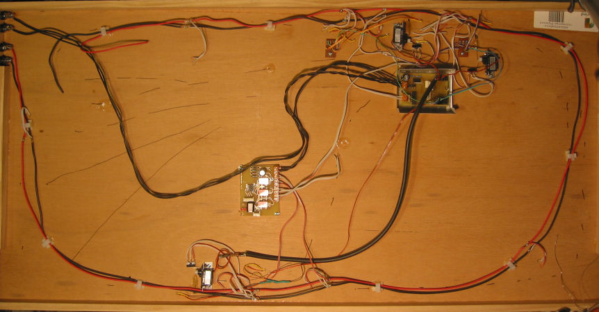
At the top left corner you can see the connectors for power. I have separated the DCC track power and a 12VAC source for powering other modules. The larger circuit board towards the top right is the DCC servo controller. It is used to control the RC Servos that switch the turnouts. It can control up to 8 servos. The other PCB in the middle is the automatic track reverser. The loop section of track needs to have its polarity switch as a train comes in and out of the loop.
The picture below shows one of the turnouts, and its underneath wiring.
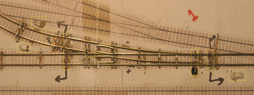
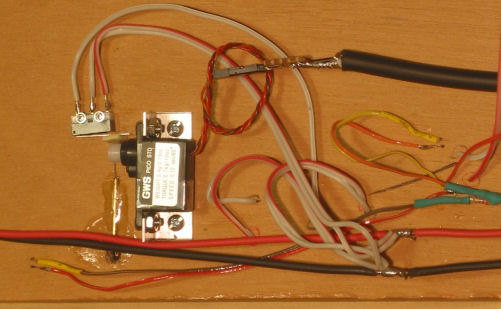
The turnout is hand laid using a Fast Tracks Turnout Fixture. The turnout throwbar is thrown using a small RC hobby servo. This is controlled by a DCC servo driver. There is also a limit switch that gets toggled when the turnout is thrown to provide the correct polarity voltage to the turnout frog. There are signaling LEDs at each of the 3 entrys to the turnout. These are controlled by the DCC servo driver.
There are many cuts in the track to isolate the power. This is done in situations like the frog and reversing loop where polarity must be switched. In other scenarios, it will be used for automatic signaling (at least the displaying of lights and reporting to a central control).