I2C Servo Controller
This is the servo controller for my robot. It uses a MC33887 H-Bridge chip to power the motor, an Atmega88 as the contoller, and an I2C interface.
It was designed to be the motion drive for the robot, but being a servo drive with position feedback, I will probably use it to rotate and elevate the turret, and possibly use it for the sonar movement.
Design
H-Bridge
I've always struggled to get H-Bridges to work properly when I build them from discrete transistors or MOSFETs. To avoid the pain, I decided to use an H-Bridge in a chip. I chose the MC33887 because of it's voltage range - 5v to 28v. I originally planned to run the robot on 12v, but I'm currently thinking 6v will be better. This keeps the options open. The chip can handle continuous loads of up to 5A and can handle PWM frequencies up to 10kHz. Although 10kHz is in the audible range, in practise it wasn't noticable.
Microcontroller
The Atmega88 has more than enough grunt to handle this project. It can be clocked at 20MHz, has more than enough timers and PWM outputs, and has built-in I2C support.
Isolation
Because we are controlling motors that can, firstly, be running at high voltages, and secondly, generate high voltage transients, it was important to isolate the controller from the I2 bus. If a fault or short occurred, it could damage the main cpu.
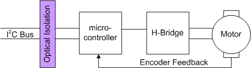
Version 1 of the controller used optical isolation at the I2C bus. The logical separation is shown below.
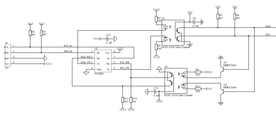
The implementation of this isolation is documented in a few sources. I used the article at www.embbed.com. Link here. This was my circuit...
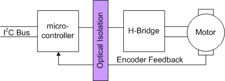
I had a couple of issues with this circuit. Firstly, it uses the P82B96 bi-directional bus buffer; exotic and expensive in Australia. Secondly, you don't have access to the I2C Vcc signal. This means the motor side has to be powered, or another external source Vcc source supplied to access the microcontroller. So, in version 2, I put the isolation between the microcontroller and the H-Bridge and motor. Logically it looks like this...
The circuit a little simpler, but requires more opto-isolators. It also means I can't get access to the H-Bridge analog signals, in particular, the current sense line. I'm still not sure this was the best decision.
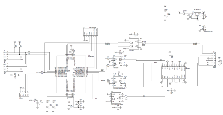
Here is the schematic for the complete version 2.1...
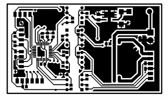
Here's the PCB artwork...
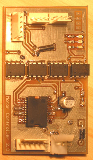
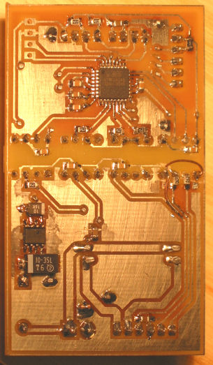
Version 2.1 had some modifications for the encoder inputs. The encoders on the motor I was using were open collector outputs. The circuit will probably need to be modified for other types of encoder output. Here's the version 2.0 PCB with jumper fixes.
The Motor
This is the motor I created the controller for.
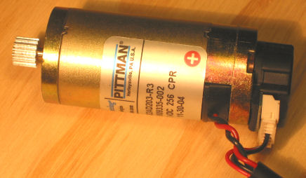
I got a dozen of these on ebay. Brushed DC, 30.3 volt, 256 cpr encoder, 30mm diameter, and about 60mm long.
Firmware
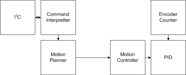
A logical diagram of the firmware is shown below...
I2C Interface
The controller communicates with the outside world via the I2C interface. It is an I2C slave, so all commands and responses are initiated by the master. Below is a list of commands supported by the controller. Data is sent little-endian.
| Command | Code | Message Format | Description |
| ENABLE_MOTOR | 1 | <1><1> | Enables the motor and will now start executing movement commands. |
| DISABLE_MOTOR | 2 | <2><0> | Stops responding to movement commands. Motor will free wheel. |
| MOVE_TO_CMD | 3 | <3><Byte0><Byte1><Byte2><Byte3> | Absolute move to position in steps |
| MOVE_CMD | 4 | <4><Byte0><Byte1><Byte2><Byte3> | Relative move in steps |
| SET_SPEED_CMD | 5 | <5><Byte0><Byte1><Byte2><Byte3> | Move at a set speed in steps/sec. For safety this command should be limited in run time using the SET_SPEED_PERIOD_CMD command and then repeatedly called before the time runs out. |
| SET_SPEED_PERIOD_CMD | 10 | <10><Byte0><Byte1><Byte2><Byte3> | Set the time a SET_SPEED_CMD will continue for (ms). |
| SET_MAX_SPEED_CMD | 11 | <11><Byte0><Byte1><Byte2><Byte3> | Set the max speed in steps/second. This is stored in the eeprom. |
| SET_ACCEL_CMD | 12 | <12><Byte0><Byte1><Byte2><Byte3> | Set the max acceleration in steps/second/second. This is stored in the eeprom. |
| GET_SPEED_CMD | 20 | <20>? | Not yet implemented. |
| GET_POSITION_CMD | 21 | <21>? | Not yet implemented. |
| QUERY_STATE | 22 | <22> | returns <status><pos0><pos1><pos2> where status is a mask, MotorFault = 0x01, PositionError = 0x02, MotorEnabled = 0x04 and pos is the 3 least significant bytes of the current position. |
| SET_ADDRESS_CMD | 40 | <40><0x42><0x24><0x00><Address> | Sets the I2C bus address and stores it in the eeprom. |
| SET_PID_P_CMD | 41 | <41><LSB><MSB> | Changes the PID P parameter and stores it in the eeprom. |
| SET_PID_I_CMD | 42 | <42><LSB><MSB> | Changes the PID I parameter and stores it in the eeprom. |
| SET_PID_D_CMD | 43 | <43><LSB><MSB> | Changes the PID D parameter and stores it in the eeprom. |
| SET_PID_SCALE_CMD | 44 | <44><LSB><MSB> | Changes the PID Scale parameter and stores it in the eeprom. |
| SET_PID_ERROR_CMD | 45 | <45><LSB><MSB> | fault if PID error gets above this. 0 to disable. Value is stored in the eeprom. |
| GET_ADDRESS_CMD | 60 | <60> | Returns the one byte address. |
| GET_PID_P_CMD | 61 | <61> | Returns the two byte P value. |
| GET_PID_I_CMD | 62 | <62> | Returns the two byte I value. |
| GET_PID_D_CMD | 63 | <63> | Returns the two byte D value. |
| GET_PID_SCALE_CMD | 64 | <64> | Returns the two byte Scale value. |
| GET_PID_ERROR_CMD | 65 | <65> | Returns the two byte Error value. |
The I2C interface was a pain in the neck. Coding both the slave and the master together proved tricky.
Motion Controller
The motion controller is responsible for moving the motor; either accelerating, running, decelerating, or remaining stopped. The implementation is quite simple (see MotionUpdate()). All important variables are pre-calculated in the Motion Planner module. The motion controller is then called 1024 times per second to increment and decrement the variables.
A typical motion path will have acceleration, run and deceleration. The motion planner pre-calculates the acceleration time, run time, run time fraction and deceleration time.
The motion controller does the following "computations" 1024 times per second...
if accelerating
AccerlationTime = AccerlationTime - 1
CurrentPosition = CurrentPosition + CurrentVelocity
CurrentVelocity = CurrentVelocity + Acceleration
if running
RunTime = RunTime - 1
CurrentPosition = CurrentPosition + CurrentVelocity
if decelerating
DecelerationTime = DecelerationTime - 1
CurrentVelocity = CurrentVelocity - Acceleration
CurrentPosition = CurrentPosition + CurrentVelocity
That's it. Complex motions, like stopping and changing direction are computed by the Motion Planner. Moving the motor to this position is handled by the PID loop.
PID
The PID loop, in combination with the Motion Controller, moves motor or locks it in place. The Motion Controller calculates the new position the motor needs to be at. The PID loop then compares the current position to the target position, computes the error, then moves the motor accordingly. This made the implementation a whole lot simpler than trying to generate precise step/direction pulses for an external driver.
The PID loop is called 1024 times per second, after the Motion Controller has been called. It implements a standard PID equation using integer math...
Output = (Kp*nPropError + Kd*(nPropError - nPrevErr) + Ki*nIerror) >> Scale;
All variables are 16 bit integers. The sign of the Output value is used to control the direction of the motor and the magnitude is used to control the PWM signal controlling the H-Bridge.
A flag is set by a timer interrupt 1024 times a second. The PID loop and motion controller functions are then called by the main loop when this flag is set. Therefore the timing of these routines is not very precise, but they do not need to be.
Encoder Counter
The encoder lines A and B are connected to pins PC0 and PC1. The AVR pin change interrupt is used to detect changes of these two pins. This is used to increment or decrement the encoder counter.
Motion Planner
The Motion Planner module is responsible for computing the movement parameters for the Motion Controller. The motion calculations are based on the standard motion equations, but use a fixed time period to reduce the calculations to integer math.
The basic motion equations are shown below.
x = x0 + v0 t + ½ a t2
v = v0 + a t
We only use a fixed acceleration, so a is a constant.
A typical motion path accelerates from zero, runs, then decelerates to a stop. This is shown in the figure below.
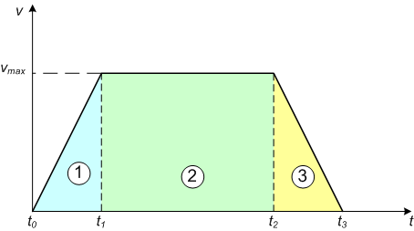
To perform motion, the 3 equations represented in the graph need to be solved to find the time we accelerate, travel, then decelerate...
1) x1 = ½ a (t1-t0)2
2) x2 = vmax (t2 - t1)
3) x3 = ½ a (t3-t2)2
We also know...
x1 + x2 + x3 = distance we wish to travel, and
there is a vmax, the maximum velocity, set by our motor, that we must not exceed.
Of course, this assumes a long travel. If the distance is short, there will be no travel, just acceleration and deceleration. The equations become more complex if v0≠0 and x0≠0.
The basic motion equations use real numbers. To lighten the load on our microcontroller, we use integer math, and break time into discrete intervals. This changes the motion equations with respect to x, as can be seen in the graphs below.
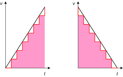
Now, our equation becomes,
x = x0 + v0 t + ½ a t2 - ½ a t
That is what the motion planner does. Solves those equations to compute the acceleration, run and deceleration times of a typical motion segment. It calculates motion from stop, and will also calculate updates when it is already moving or accelerating/decelerating.
The development of the motion planning code was done under windows. The motion code is pretty standard C, so it could be developed on the windows platform on a fast PC and thoroughly exercised through all possible test scenarios.
Firmware
The source for the firmware can be found here ![]() .
.
The test harness to drive the controller can be found in the I2C Library on the SerialMon page.
Next
I'm sure more improvements will come if I every use the controller. Unfortunately the motors are a little bit too big to fit inside the missile launcher robot base as the drive motors; I need smaller motors or some clever hackery. The controller has been thoroughly tested, so I am confident it works.
To drive the tank tracked missile launcher requires two motors and controllers. I'll need to either add commands to synchronise the movement, or create a new version with two H-Bridges to support two motors.
There's also a couple of unimportant unimplemented commands.
The encoder inputs need to be changed to make them support different encoder output types. Maybe they don't need to be opto-isolated.
And I need to double check my opto-isolation to see which type is better.