Lathe Leadscrew Handwheel
Here's a project that I've wanted to do for a while: a handwheel for the leadscrew. I've always had problems with the finishing cut, not being able to get a very good finish. I suspect it has to do with getting the spindle speed, feed rate, tool shape, tip radius, and tool sharpness just right. So to help me feed a little slower and more precise, I built the handwheel.
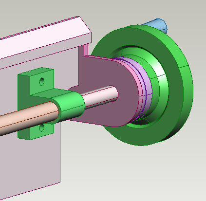
This design is based on the drawings posted in the yahoo 9x20Lathe group, photos section. The design was for a 7x12 lathe, but it was easy enough to modify to fit mine.
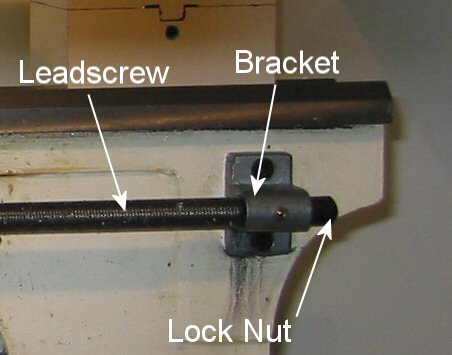
The main difference between the 9x20 and 7x12 lathe is the way the lead screw is held at the end. The 7x20 is held freely in the bracket. The 9x20 leadscrew is threaded on the end and has a lock nut to hold it firmly against the bracket. This is shown below.
My first idea for extending the leadscrew was to create a threaded shaft that would screw onto the end of the leadscrew in place of the lock nut. The problem with this was when tightened, it did not extend collinearly.
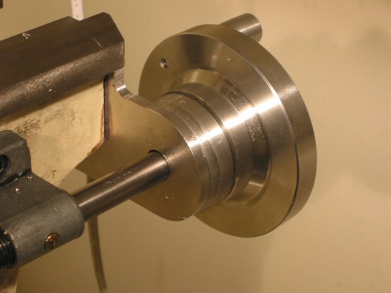
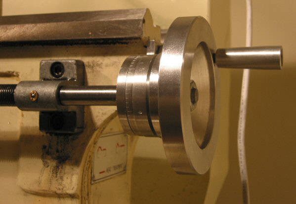
So I ended up following the 7x12 plans to bore a hole into the leadscrew. I bored the hole 6mm in diameter about 60mm deep through the threaded end. This was a fallback so I could still use the lock nut. All was fine until the drill bit binded in the hole and snapped off the small threaded section. This was a blessing in disguise, as can be seen in the photo below, the extension shaft fit properly and tightly against the bracket.
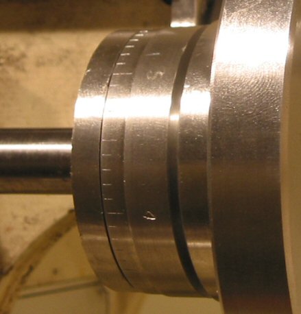
The graduated dial, shown in detail below. This was built using the spindle arbor, so it could be turned then move to the rotary table to be indexed. It doesn't look too bad in the photo, but I messed up the numbering by stamping an upside down 2, instead of a 5. I tried to fix it by shaving a bit off the radius, however I stamped the numbers while it was still held in the chuck and knocked it out of alignment.