NC Rotary Table
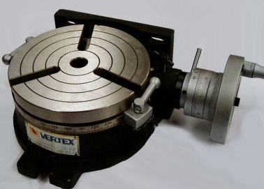
The table can be used horizontally as shown in the photo to cut circles and arcs, or it can be placed on it side to index a part, for example, cut the hex flats on a screw head. The hole in the center is an MT3 taper which is the same as my lathe.
The handle turns a worm gear that rotates the table. It has a 90:1 ratio, meaning it takes 90 turns of the handle to rotate the table 360° . And that is the reason why I want this automated. I really don't have the patience to count that many turns. And when indexing, it is easy to mis-count.
Design
Hardware
The plan was to remove the handle and mount the stepper motor directly to the handle shaft. This would require some mounting hardware. (Click for a more detailed pdf file).
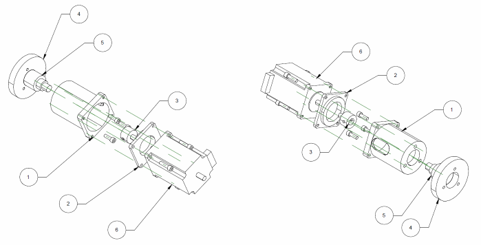
| 1 | Motor Mount Main |
| 2 | Motor Alignment Coupler |
| 3 | Spindle Coupling |
| 4 | Rotary Table Mount Face |
| 5 | Rotary Table Spindle |
| 6 | Motor |
The motor mount needs to hold the motor at one end and attach to the rotary table at the other end. When mounted, the motor spindle must be in line with the rotary table handle spindle. This was a bit advanced for my turning skills at the time, so I made the mount in two pieces.
The motor mount is made up of the Motor Mount Main (1) and the Motor Alignment Coupler (2). These parts were turned on a lathe. The Motor Mount Main is a cup that screws on to the rotary table mounting face. The Motor Alignment Coupler, aligns the motor to the Motor Mount Main.
The Spindle Coupling (3) is a small adaptor that reduces the diameter of Rotary Table spindle from 12mm to 8mm to match the diameter of the stepper motor shaft. Initially, I used a piece of automotive rubber hose and couple of hose clamps (jubilee clips) to connect the two together, but it kept slipping, and I replaced it with a proper coupler.
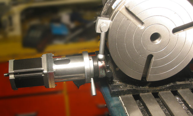
The assembled motor and mount is shown in the photo below...
Stepper Driver
To control the motor, I planned to make my own stepper controller. The design was based on the LMD18245, a 3A, 55V Full-Bridge motor driver. This is a more advanced version of the LMD18200. The big difference is a 4-bit interface to control the current through the motor winding. By applying the correct sequence of pulses, micro-stepping can be implemented easily. A pair of these on a PCB with a bit of support circuitry (using the datasheet reference design) is all that is needed to drive a stepper motor.
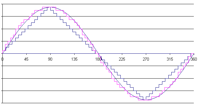
The 4-bit current control means 16 different current levels can be applied. By using a look up table, a proper driving wave can be generated. Note - to correctly drive in micro step modes, a sine wave (or simulated sine wave) needs to be produced. Many programmers of the LMD18245 just iterate through the values linearly, creating a triangle wave. The LMD18245 datasheet shows a couple of low micro step count examples (Figure 11 and Figure 13).
To calculate the lookup table, I used a spreadsheet with the following data...
| A | B | |
| 1 | 0 | =ROUND(SIN(A1/180 *PI())*15,0) |
| 2 | 5 | 1 |
| 3 | 10 | 3 |
| 4 | 15 | 4 |
| 5 | 20 | 5 |
where column A contains the micro step angles, and column B contains the formula to calculate the digital current setting (the formula is only shown in cell B1).
That table shows the start of the sheet, with steps every 5°. Over 90 degrees, this gives 18 micro steps. This is actually a pretty bad example because the error is very high. A smaller number of micro steps should be used. The 18 micro step electrical wave, a true sine wave and a linear implementation are compared in the chart below...
As I mentioned above, "I planned" to do this. In fact I did build a stepper controller and used it as the first version, but the PCB was poorly designed and I had problems with a poorly secured heatsink breaking pins and shorting with logic power supply. It also had speed limitations. In the end I just switched to a Gecko G201 stepper driver. This made the control a lot simpler, requiring only a Step and Direction line, rather than Brake, Direction, M1, M2, M3, M4 for each full bridge. I haven't shown my schematic here, but a good example of another design (schematic and PCB) can be found here.
Controller
The controller for the rotary table is self contained. It comprises a keypad, LCD display and microcontroller (atmega162) to control the stepper driver. I don't have a version of the circuit diagram available, however it is very simple, with the microcontroller in the middle and a few header surrounding it to connect to the peripherals.
For the display, I used a 20x4 back lit LCD. The 4 lines of information is quite useful. It allowed me to display the position of the table in steps and degrees at the same time (useful for debugging). It is a standard LCD.
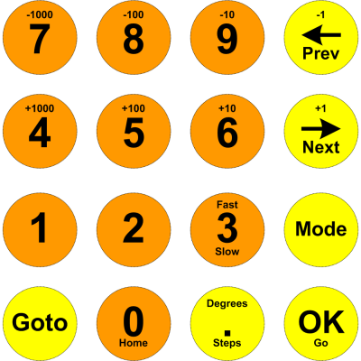
For a keypad I used a 4x4 splash proof membrane keypad, an IN2TEC (C&K) 4244A1 which I got from RS Components. The keypad is flat with a self adhesive back which made it easy to install on a plastic enclosure. It comes with a set of predefined key labels, but can be replaced with your own. My key layout is shown below. This is taken from the graphic used to print the key labels.
To this I added a couple of push button switches, one for stop, and one for emergency stop. The emergency stop is a 240v line to a relay to cut power to all components, so it had to be a separate high voltage rated switch. The stop switch is also illuminated so I can see when the table is moving.
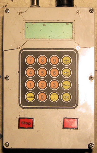
A photo of the enclosure is shown below. The box in the picture is supposedly a tough polycarbonate, but as you can see, it tends to shatter when dropped and having things dropped on it. Replacing this with an ABS enclosure is on the TODO list. The button you can't see because of glare is the Emergency Stop button.
Software
The table below lists the functions performed by the rotary table controller.
| Mode | Description | ||||||||||||||||||||
| Jog | In Jog mode, the top two rows are used to manually move the rotary table. Each key press will move the motor the number of steps printed on the key. The mode can be changed from Steps to Degrees, where 1000 represents 1.000 degrees. In jog mode, the Goto button will move the table to the commanded position, either in degrees or steps. Press Goto, enter the position using the number keys and decimal point key, then press OK. Press the Home key to set the current position to 0° (or steps). The Fast/Slow button can be used to toggle between the preset fast speed or slow speed (set in Setup mode). | ||||||||||||||||||||
| Division | In Division mode, the 360° of the table is divided up in to an integral number of even divisions. The number of divisions will be prompted for. Then use the left and right arrow buttons to move through the divisions. The Goto button can be used to jump to a particular division number. The first division always starts at 0°. | ||||||||||||||||||||
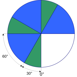
| Degrees | In Degrees mode, a series of divisions are defined by
specifying the number of degrees between them. These
degree patterns are then repeated. The degrees do not
need to add up to 360°. For example, defining two
degree segments of 30° and 60° gives the following
repeating pattern...
|
||||||||||||||||||||
| Continuous | Continuous mode does as its name implies - it rotates continuously until the stop button is pressed. The speed is controlled by the 1000, 100, 10, 1, -1, -10, -100, -1000 buttons. Each key press adjusts the speed. To change direction keep reducing the speed until it goes to zero, then continue reducing the speed until the speed value changes to negative (or positive depending on which way you are traveling). It is best to stop the table before changing direction - dodgy software! The OK key is used to start moving. | ||||||||||||||||||||
| Setup | Setup mode is used to configure the controllers
parameters. These are...
|
Software Implementation
The calculations and movements are always done in steps. Calculations are also done in absolute values, not relative. For example, if I am at 33.7° and jogging forward 1°, rather than adding the steps for one degree to the current position, the target position is determined, in this case 34.7°, converted to steps, and then the difference in steps is used to determine the new position. This stops accumulation errors.
The motion control code is pretty dated. It is based on the algorithms described in the Gecko Yahoo group, in the MOVEAXIS.GIF file. It will accelerate and move smoothly and accurately. There are still some issues, however, trying to make changes when the table is already in motion. This needs to be updated.
The firmware can be found here
![]() .
.
In Use
The table has worked well. It has been used mainly for indexing; machining flats on shafts, or cross drilling. For this I usually use an ER32 Collet set with MT3 arbor, or the Lathe Spindle Arbor (See the photos at the bottom).
It was also used to create the Large Lathe Steady. It was because of this project that I added the continuous mode. I needed to cut a large diameter ring in some thick steel plate. In continuous mode, I just lowered the Z axis a bit after each revolution.
Todo
- Replace the enclosure. Use ABS this time. Maybe find something a bit more compact.
- Examine different keypads. Although the keypad has worked well, its major weakness is that it is self-adhesive and stuck to the electrical enclosure. When I replace the enclosure, I don't think I'll be able to remove the keypad without damaging it.
- Update the motion control software to better handle changes while in motion.